We’ve identified multiple critical software vulnerabilities in QSEE, Qualcomm’s Trusted Execution Environment (TEE), on Qualcomm IPQ40xx-based devices (see post #1 and post #2). We exploited these vulnerabilities in order to disable the secure range checks performed by QSEE in order to execute arbitrary code at the highest privilege (see post #4). As these vulnerabilities are software vulnerabilities, they were easily fixed by Qualcomm after we disclosed them responsibly.
As you may have already raelized, at Raelize we like to look further than just software vulnerabilities. Therefore, we decided to analyze the resilience of the Qualcomm IPQ40xx-family of chip towards Electromagnetic Fault Injection (EMFI). We used the Linksys EA8300 WiFi router (see post #2).
We are fully aware that FI attacks are typically out of scope for a TEE threat model. Actually, ARM specifies this very clearly in their documentation. However, TEEs are also used for devices where FI attacks are considered a reasonable threat. Therefore, even if FI attacks are out of scope for a TEE according to ARM, they may not be for specific devices. The TEE on such devices, may be used to protect assets interesting for an attacker, making it an (very) interesting attack surface. Whenever the underlying platform (i.e. hardware) is vulnerable to FI attacks, the security of a TEE can be (easily) compromised as we will see in this post.
At first, you may think that the ARM TrustZone hardware primitives (e.g. NS bit, TrustZone controllers, …) are the most interesting target for a FI attack. However, we decided to target the processor executing the QSEE software in order to show that other approaches are very effective as well.
EMFI
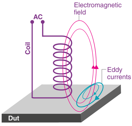
We use Riscure’s EMFI tooling to inject EM glitches in the chip. This tooling drives a high voltage through a coil in order to generate an electromagnetic field. This allows us to introduce faults at the transistor level due to eddy currents within the chip’s circuitry. The concept of EMFI is shown in the picture below (source).
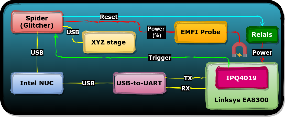
A diagram of our setup is shown below. We used the Riscure Spider, Riscure EMFI Probe and Riscure XYZ stage. Additionally, we use a solid-state relay to control the external power supply of the target. We control the all hardware using Riscure’s Inspector FI Python framework in order to, among others, the glitch parameters (i.e. position, timing and glitch power) completely automatically.
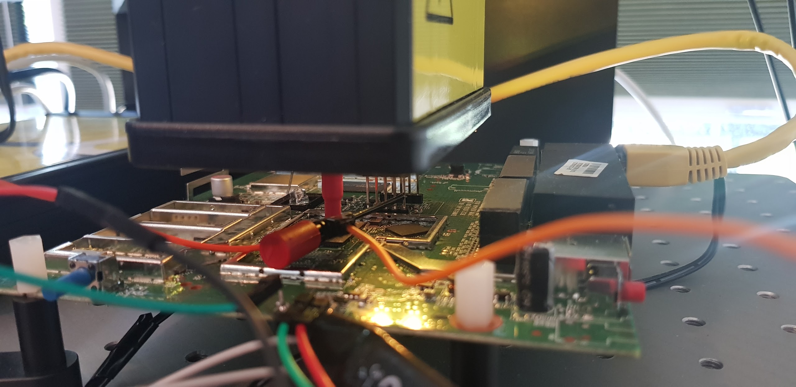
We perform the EMFI attack by placing the EM probe directly on the chip’s surface. In order to do so, we opened up the target and removed the chip’s heatsink. We made no other physical (invasive) modifications. An actual picture of the chip is shown below.
We often get asked if our lab-grade tooling made by Riscure is really required to perform our attacks. We believe it’s definitely possible to perform the same type of attacks using easier to obtain tooling like NewAE’s ChipShouter or to build your own tooling. However, the tooling we use makes it easier to identify and reproduce the attacks. Nonetheless, we would love to hear from you if you’re working on reproducing our research using other tooling.
Characterization
Whenever possible, we like to start with a FI characterization test in order to determine if the target is vulnerable. We implement the characterization code, which is shown below, as an U-Boot standalone application. The goal of this characterization test is to identify good glitch parameters (i.e. location and power) in a semi-controlled environment. By repeating the target instruction (i.e. add instruction) we increase the chances for success.
uint32_t *trigger = (uint32_t *)(0x0102f004);

if(cmd == 'A') {
    uint32_t counter;

    *trigger = 0x0;                     // 1. set trigger high

    asm volatile (
            "mov r0, #0;"               // 2. set counter to 0
            "add r0, r0, #1;"           // 3. increase counter
            < repeat 10,000 times>
            "mov %[counter], r0;"
        : [counter] "=r" (counter)
        :
        : "r0" );

    *trigger = 0x3;                     // 4. set trigger to low

    printf("AAAA%08xBBBB\n", counter);  // 5. print counter on UART
}
We use a GPIO pin of the target as a trigger to time the characterization test. This allows us to exactly inject glitches when the add instructions are executed. If the resulting counter value that’s printed on the serial interface is differently than expected, we know we successfully modified the expected behavior of the software.
After performing roughly 20,000 experiments across the chip’s surface, we observed different output, some of which are shown below. Most interesting of course, are the experiments where a modified counter value is returned. An indication that the target is vulnerable.
| Type | Response |
|---|---|
| Expected | AAAA 00002710 BBBB |
| Reset/Mute | no output |
| Success | AAAA 0000270f BBBB |
| Success | AAAA 0000270e BBBB |
| Success | AAAA 0000270b BBBB |
We plot the experiments based their classification in order to determine what’s a good location for the EMFI probe, which is shown below. Interestingly, we observe that all successful experiments occurred in a specific area on the chip’s surface.
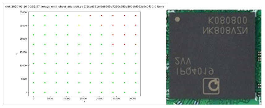
Even though we determined that the target is vulnerable to EMFI, we don’t know yet if we can actually alter the QSEE software itself as we targeted only U-Boot code so far. However, as both U-Boot and QSEE are executed by the same processor, just with a different NS bit, we are confident the vulnerable locations we identified will yields faults in QSEE software too. Therefore, we place the probe on one of the locations where we observed a successful glitch. This allows us to target QSEE software without moving the probe, effectively removing the spatial parameter from the glitch parameter search space.
Disabling secure ranges
As earlier mentioned, we decided to target the QSEE software instead of the the underlying ARM TrustZone hardware primitives (e.g. NS-bit, TZASC).
We know from our earlier conducted QSEE software analysis that various security enforcements are entirely implemented by software. This includes for example the secure range checks which are performed by the SMC handler routines on the arguments received from the Rich Execution Environment (REE).
We decided to target a SMC handler routine that does not include any software vulnerability. One of the candidates that we identified is tzbsp_fver_get_version for which the decompilation is shown below.
int tzbsp_fver_get_version(uint32_t a1, uint32_t *a2, uint32_t a3)
{
    uint32_t v4 = 0;

    if ( !is_ree_range(off_87EAB290, a2, a2 + 3) )      // range check
        return 0xFFFFFFEE;
    if ( a3 < 4 || !a2 )                                // argument check
        return 0xFFFFFFF0;
    *a2 = 0;                                            // NULL-write
    do {
        if ( dword_87EABB48[2 * v4] == a1 )             // must fail
          *a2 = dword_87EABB48[2 * v4 + 1];
        ++v4;
    } while ( v4 < 0xC );
    return 0;
}
The is_ree_range function checks if a2 and a2 +3 point to non-secure memory. This argument is passed from the REE and we assume that this argument is under control of the attacker. Simpler said, this function verifies if the buffer provided from the REE overlaps with secure memory. If it does, tzbsp_fver_get_version will immediately return 0xFFFFFFEE.
Using an EM glitch, we aim to to bypass the restrictions enforced by the is_ree_range function. This allows us to execute the remainder of tzbsp_fver_get_version in order to write NULL to an arbitrary address (incl. secure memory).
We communicate with tzbsp_fver_get_version from the REE using an U-Boot standalone application, which is shown below.
uint32_t a1 = 0xdeadbeef; // pass argument check
uint32_t a2 = 0x87EAB204; // secure memory address
uint32_t a3 = 4;          // pass argument check
uint32_t a4 = 0;          // NA

uint32_t *trigger = (uint32_t *)(0x0102f004);

// trigger up
*trigger = 0x0;

// calling tzbsp_fver_get_version()
uint32_t ret1 = scm_call_r(0x6, 0x3, a1, a2, a3, a4, 3);

// trigger down
*trigger = 0x3;

// calling tzbsp_fver_get_version()
uint32_t ret2 = scm_call_r(0x6, 0x3, a1, a2, a3, a4, 3);

// printing to serial interface
printf("AAAA%08x%08x%08xBBBB\n", ret1, ret2, *(uint32_t *)a2);
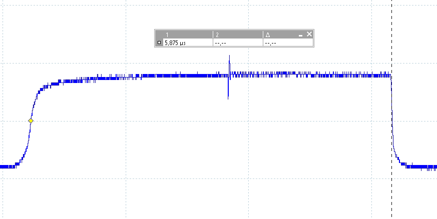
We use a GPIO signal as a trigger to time exactly when tzbsp_fver_get_version exactly is executed. The EM glitch is injected exactly between the moment the trigger is set high and set low, which takes approximately 5.875 microseconds (see picture below).
In the above code example, by writing NULL to 0x87EAB204, we disable one of the secure ranges defined in the secure range table. More details on how this exactly works will be explained in more detail in post #4. For this post, it’s sufficient to raelize that a successful attack will disable the restrictions enforced by the secure range check for each SMC handler routine.
We execute tzbsp_fver_get_version a second time, with the same destination address, without injecting any glitch, in order to verify whether the attack was successful. If the secure range is successfully disabled, is_ree_range will consider any address passed from REE in a2 as valid, including secure memory addresses. The write to the secure memory address will then successfully complete as well.
Moreover, in the last line of the code, we dereference the secure range flag field from REE. This is done in order to verify that the malicious TEE write actually happened. It should be noted that, due to the (mis)configuration of the target, we are able to read secure memory from the REE.
Typically, this is not possible, or should NOT be possible, as, otherwise, any secret handled by QSEE would be exposed to the REE. In our setup, we only use this mis-configuration to double verify if an experiment is successful or not.
We expect at least the following type of results: expected, successful, processor exception and reset/mute experiments. The table below indicates the serial interface output we expect to receive for each result.
| Type | Response |
|---|---|
| Expected | AAAAffffffeeffffffee00000002BBBB |
| Success | AAAA000000000000000000000000BBBB |
| Exceptions | undefined instruction |
| Reset/Mute | no output |
We performed roughly 300,000 experiments where we inject EM glitches within the entire attack window. We give each experiment a randomized power between 10% and 100%. The EM probe itself is fixed to a vulnerable location on the chip’s surface that we identified earlier. This entire campaign lasted roughly 12 hours. We plotted all experiments as is shown in the figure below.
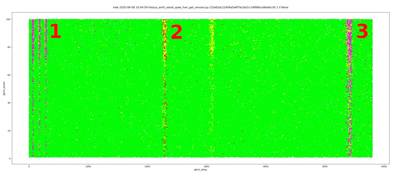
We can summarize the plot as follows:
- In area 1 we observe many processor exceptions. An indication that the glitch is injected while U-Boot code is being executed. In other words, we inject the glitch too soon.
- In area 2 we observe many successful experiments. An indication that this is exactly the moment where we wan to inject the glitch. Moreover, this proves that this is the moment where
tzbsp_fver_get_versionis executed. - In area 3 we observe many processor exceptions. An indication that the glitch is injected while U-Boot code is being executed. In other words, we inject the glitch too late.
The success rate is fairly low. Most experiments, where we observe the expected response, are not successful. Nonetheless, we observe a success rate of 0.05%, which, at our testing speeds, translates to roughly 1 successful experiment every 5 minutes.
However, if we set the glitch parameters (i.e. glitch delay and glitch power) to that of a successful experiment, we observe a success rate of 5%, or roughly 1 successful experiment every 20 seconds. This shows that the reproducibility of bypassing the range check is very high. We feel comfortable saying that we are able to bypass any of the configured range checks, by using an EM glitch.
Achieving code execution
We know from our software vulnerability analysis that we are able to achieve code execution after the secure ranges are disabled. This will be described in full details in post #4.
Conclusion
We demonstrated that the Qualcomm IPQ40xx family of chips are vulnerable to EMFI. We exploited this vulnerability in order to bypass a secure range check performed by QSEE. This allows us to write a restricted value to an arbitrary address (incl. secure memory).
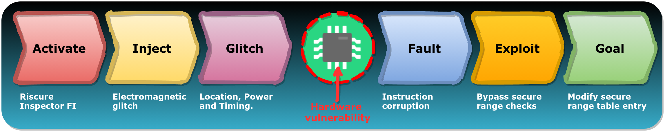
The attack can be described using our FIRM, as shown in the figure below. Once the optimal glitch parameters are found, the attack can be reproduced once every 20 seconds, which is a very high success rate.
We targeted the processor executing the QSEE software instead of the ARM TrustZone hardware primitives. This means that hardening these hardware primitives is not sufficient protection for hardening a device against FI attacks. We believe that hardening the processor itself is fundamental.
The impact of software vulnerabilities is typically much larger than (hardware) attacks that require physical access. Mass exploitation is for example typically not possible with FI attacks. Nonetheless, we like to stress that these type of attacks should not immediately be considered a harmless threat. For instance, they are often used to gain access to secured code or data in order to identify easier to exploit (software) vulnerabilities.
As a TEE is used to secure important assets, it will always be a very interesting target, also for FI-capable attackers. Of course, especially for devices where FI attacks are specifically included in the threat model and other components (e.g. ROM, bootloaders) are already hardened.
We’ve disclosed this vulnerability responsibly to Qualcomm using a coordinated disclosure process. They indicated that FI attacks are out of scope for the Qualcomm IPQ40xx family of chips and therefore the vulnerability will not be fixed. This choice is understandable, considering the typical TEE threat model. However, as a result, these chips will be vulnerable forever…
- Raelize.