TL;DR: We used Claude Code to reproduce a Fault Injection attack where Secure Boot is bypassed on an Espressif ESP32 SoC. We gave Claude full control to all the hardware tooling. All software tooling was written by Claude using third-party libraries. None of the code was written by humans. All this was created organically while glitches were being injected in the background (i.e., no downtime). This type of agentic workflow for finding/exploiting hardware vulnerabilities is likely here to stay, as it will be for software vulnerabilities.
Contents
- Time line
- Introduction
- Let’s get started
- Setup
- Programming the flash
- Reading the serial
- Glitch Monitor
- Attack
- Caveats and reflections
Timeline
Day 1:
- 18:00: Returned home from holiday after driving the entire day thinking about doing this.
- 22:00: Me: “We are going to bypass ESP32’s Secure Boot using ChipWhisperer Husky.”
- 22:15: Manually building the setup with the necessary hardware tooling
- 23:00: Me: “Bunch of stuff via USB; I will guide you a bit; figure out everything else yourself.”
- 23:00 → 00:30: 🪄
- 00:30: Me: “Enough. I go to bed.”
Day 2:
- 11:00: Me: “Let’s continue yesterday’s session.”
- 11:00 → 12:15: 🪄
- 12:15: Me: “That looks interesting; you successfully bypassed Secure Boot!”
- 12:15 → 22:00: 🪄
- 22:00 → 24:00: Blog post reviewed and published.
Introduction
We reproduced a real Fault Injection attack, where ESP32’s Secure Boot V1 is bypassed using Voltage crowbar glitches, using Claude doing all the engineering. The AI did it all. From configuring the ChipWhisperer Husky and the Riden RK6006 lab supply, to writing the attack script, debugging hardware quirks, reverse-engineering the boot ROM with a sub-agent, building a live monitoring dashboard while the campaign was running, and tuning parameters across thousands of glitch attempts. We supervised, asked questions, and looked at the dashboards it created for us.
This is among the first publicly documented Fault Injection attack carried out with AI assistance. For more Claude-driven FI work, see the experiments/attacks documented by Adam Laurie. We’re sharing this not because the Secure Boot bypass itself is novel, that ground has been already covered in our previous blog posts, as well as in research conducted by others. What’s new here is the workflow, which is likely here to stay.
Disclaimer: The attack described in this blog post is only applicable to ESP32 V1 and has since been mitigated by ESP32 V3 (see Espressif’s Impact Analysis for more details). Note, the attack is mitigated by modifying the ROM code, the ESP32 V3 is still vulnerable to Fault Injection attacks (see our other research).
Let’s get started
We simply kicked-off this adventure by telling Claude what we were going to do.
Me: “We are going to bypass ESP32’s Secure Boot using ChipWhisperer Husky.”
Moreover, we told it to store everything it learns in a wiki format we like, which allows us and Claude to remember what we are working on.
Me: “Store and keep track of everything you learn using Hugo and the relearn theme.”
Then we connected all the required tooling via USB to a freshly installed laptop with Ubuntu 26.04 LTS. Moreover, we give Claude full power using --dangerously-skip-permissions, as the laptop is not used for any other purpose.
Setup
The hardware was wired up by hand. It’s the same setup we use for our TAoFI training. Claude wrote all tooling from scratch, relying on third-party libraries where possible. For example, we used chipwhisperer for the Husky, picosdk for the PicoScope, pyserial for UART, an open-source RK6006-Python-Module for the lab supply.
Here is a picture of the actual setup:
The actual setup used for this AI adventure.
Early on we asked Claude to keep track of what it was building:
Me: “While you learn about all the tooling; please keep updating a diagram of all the connections.”
This resulted eventually in the following diagram:
Diagram of the setup indicating how everything is connected.
Note, the RTC and CPU power domain are glitched together, at the same time, which is needed due to an internal LDO that connects these power domains together. Just glitching the CPU power domain, does not result in the right type of glitches. This is something we already know and in a fully unknown black-box setting should require some manual intervention for trial and error (i.e., what power domain to glitch).
Target
The target is Espressif’s ESP32 SoC mounted on our TAoFI Target development board, which we also use for our advanced FI training named The Art of Fault Injection (TAoFI).
We simply instructed Claude to learn more about this target:
Me: “Learn about the target here: https://github.com/raelize/TAoFI-Target"
The board hosts an Espressif ESP32 SoC (rev 0) and exposes everything an attacker needs: separate power-domain headers , SPI flash signals routed to a header, RESET / IO0 broken out, and an UART connector. The availability of all these signals in a convenient manner decreases complexity for an effective FI setup compared to a real product based on the ESP32 SoC where you may need to do more (invasive) modifications.
The TAoFI target board
The chip is configured with Secure Boot V1 enabled in efuse (i.e., ABS_DONE_0 is set), and a modified bootloader with an invalid signature. The ROM code performs a CRC which fails due to the modification which is fixed as well. All of this information was already known to us as we perform this attack in our training. However, figuring these things out from a black-box perspective is not that difficult, it’s actually done by 100s of our students without issues.
Riden RK6006
We use the Riden RK6006 to deliver an arbitrary, programmable voltage to the RTC + CPU power domains of the ESP32. The PSU exposes a USB-CH340 serial interface, so the host can change the provided voltage mid-campaign (i.e., while it’s glitching). The RK6006’s hardware OVP cap is set to between 0.0V and 3.0 V, so we can never accidentally damage the chip while exploring lower-voltage corners (or burn our office down).
We pointed Claude at an existing open-source Python lib that handles the communication:
Me: “Use https://github.com/dzwer/RK6006-Python-Module for controlling the RK6006.”
Now we can control the voltage arbitrarily whenever we want and need.
NewAE ChipWhisperer Husky
The ChipWhisperer Husky is the heart of the setup. We use four TIO pins to drive and/or consume RESET, PROGRAM, SPI CS and UART TX. The glitch is injected using the HP MOSFET to short the CPU+RTC domain o ground for number of nanoseconds. All of this is reachable from Python via the chipwhisperer package.
We told Claude how we connected the various signals:
Me: “I’ve connected IO1 to UART TX, IO2 to RESET, IO3 to PROGRAM and IO4 to SPI CS.”
We helped Claude a bit by providing it a reference implementation from our training which is based on the guidance provided by NewAE. No real magic is done here, it’s using the standard API. Hence, we are confident Claude would have been successful in figuring this out from just the API description available online.
Me: “Find
g_AttackSignature.pyin your root (incl. its lib); that’s how we usually control the NewAE Husky.”
Claude learned essentially everything it needed to configure the Husky correctly:
- the
chipwhisperersetter pattern for the glitch module, e.g.:glitch.enabled = Trueglitch.clk_src = "pll"glitch.output = "enable_only"glitch.trigger_src = "ext_single"- …
- the role of the
ext_offset/repeatregisters - the canonical reset → arm → release → read → classify loop,
- coloring convention that we like to use
G/Y/R/M/Cfor outcome classification
We deliberately did not tell Claude to clone this script, only to read the library and use it as inspiration. What it produced (g_HuskyOnly.py) is materially different: a single Python process driving the Husky directly via the chipwhisperer library and doing reset / arm / fire / read in a tight loop, using Husky’s built-in edge_counter trigger module so the FPGA handles the timing-critical work, fewer moving parts, lower jitter, less code. You could say it’s a better implementation.
PicoScope 2406B
The PicoScope 2406B is the only piece of the setup that’s not used during real glitch campaigns. We use it primarily for verifying if everything is set up correctly (e.g., do we inject the glitch at the right moment in time). Having it available while glitching slows down the experiments, hence, we only use it when we need it.
We utilize three channels on the oscilloscope:
| Channel | Connected to | Purpose |
|---|---|---|
| A | Reset | Stable t=0 reference for trigger position |
| B | SPI CS | Independent count of flash transactions during boot |
| C | GlitchOut | Records the wall-clock time of the crowbar pulse |
Then we simply told Claude:
Me: “I’ve connected channel A to RESET, channel B to SPI CS, channel C to GlitchOut of Husky”
And then we simply asked Claude:
Me: “Use the picosdk python wrappers to communicate with the scope: https://github.com/picotech/picosdk-python-wrappers"
Claude wired this up with the picosdk Python wrapper. The verification scripts (pico_trace.py, cs_analog.py, pico_trace_multi.py) all use the PicoScope, but the campaign driver g_HuskyOnly.py does not — so once a setup is verified, the PicoScope can be unplugged without affecting throughput.
Espressif ESP-PROG
The ESP-PROG is an FT2232H-based USB-to-serial / JTAG adapter that Espressif ships for ESP32 development.
Me: “I’ve connected channel ESP-PROG to the UART of the target; figure out how to use it.”
The whole device is a glorified USB-UART for our purposes and used for communication. Claude figured out by itself how to communicate with the right ttyUSB device and what configuration to use (i.e., not that difficult as it’s the standard 115200 baud rate).
Programming the flash
The first concrete task we gave Claude, once the required tooling was available via USB in Linux, was to figure out how to program the flash. Normally this is done using the ESP-PROG, but the required signals, notably RESET and PROGRAM, were now under control of the Husky.
We simply asked Claude:
Me: “Your first mission is to use the ESP-PROG and ChipWhisperer Husky to program
bootloader.binto the flash usingesptool. Note, UART TX/RX are controlled from ESP-PROG and Husky controls RESET and GPIO.”
There’s no off-the-shelf script that combines those two tools the way we needed. Claude had to solve it, specifically, it had to figure out:
- How to put the chip in download mode using the Husky — Espressif’s
esptoolexpects a separate USB-to-serial adapter to drive RESET and IO0 / boot-strap. We don’t have one in the loop. Claude found that it could drive both pins via Husky’s TIO2 / TIO3 (which it had just learned from the wiring table), pulse them in the documentedboot:0sequence (IO0 low, RESET pulse, IO0 released), and then hand the UART off toesptool. - Which UART belongs to whom —
/dev/ttyUSB0is the RK6006,/dev/ttyUSB1is ESP-PROG channel A (JTAG, unused),/dev/ttyUSB2is ESP-PROG channel B (the actual ESP32 console). Claude probed/sys/class/tty/...to identify them by VID:PID, then locked the Husky-flash flow ontottyUSB2. - How to keep esptool from refusing the write — Secure Boot V1 makes flashes to addresses below
0x8000fail by default. Claude figured out (after one failed attempt) thatesptool ... --forceis required, and that the modified bootloader had to be written at0x1000exactly because that’s the offset the ROM reads its header from. - How to release the chip cleanly afterwards — pulling IO0 high again, asserting RESET once more, and then releasing it so the chip boots from the new flash contents.
The result is husky_flash.py, about 60 lines that pre-configure the Husky pins, shell out to esptool with the right flags, and re-boot the chip. From that point on, the target runs the bootloader we want it to run.
Reading the serial
The flashed bootloader was originally signed correctly — passes Secure Boot V1 cleanly (i.e., the signature is valid). This prints the following on the serial interface:
ets Jun  8 2016 00:22:57

rst:0x1 (POWERON_RESET),boot:0x13 (SPI_FAST_FLASH_BOOT)
configsip: 0, SPIWP:0xee
clk_drv:0x00,q_drv:0x00,d_drv:0x00,cs0_drv:0x00,hd_drv:0x00,wp_drv:0x00
mode:DIO, clock div:2
load:0x3fff0020,len:3896
load:0x40078000,len:7204
load:0x40080400,len:4
load:0x40080404,len:4028
entry 0x400806f0
(29) boot: ESP-IDF v5.1.1 2nd stage bootloader
... <cut>
I'm a bootloader!
We then modified a string inside the signed binary which invalidates the signature. From this point on, the target reproducibly prints the baseline secure boot check fail boot output every reset, which is the precondition for everything that follows. In other words, we are hanging on the Secure Boot check in ROM code, which we want to bypass using a voltage glitch.
This is printed on each boot with an invalid signature:
ets Jun  8 2016 00:22:57

rst:0x1 (POWERON_RESET),boot:0x13 (SPI_FAST_FLASH_BOOT)
configsip: 0, SPIWP:0xee
clk_drv:0x00,q_drv:0x00,d_drv:0x00,cs0_drv:0x00,hd_drv:0x00,wp_drv:0x00
mode:DIO, clock div:2
load:0x3fff0020,len:3896
load:0x40078000,len:7204
load:0x40080400,len:4
load:0x40080404,len:4028
secure boot check fail
ets_main.c 371
To make sure Claude correctly sees this as well, we simply ask:
Me: “Read the serial output of the target after reset.”
We use the I'm a bootloader! string, only printed with a valid signature, to determine if we bypassed Secure Boot successfully.
Glitch Monitor
Running a glitch experiments without a live view is painful. You’ll end up with many experiments that roll past in a terminal, you can’t filter, you can’t compare runs, and, by the time the campaign is over, the only artifact you have is a SQLite file. So before the very first campaign was even half-done, we asked Claude to build a live monitor, a tool with two jobs:
- keep track of results as they arrive
- visualize results so we can see the patterns
So we simply ask:
Me: “Build me a live web dashboard so I can keep track of the experiments from a browser.”
The result is campaign_monitor.py, a self-contained ~400-line Python HTTP server that reads from huskyonly.sqlite in read-only mode and serves an auto-refreshing dashboard on port 8083. It was written while the chip was glitching itself, every UI iteration we asked for landed in the live page within seconds, with the in-flight campaign continuing to write rows behind the scenes.

The Glitch Monitor with auto refresh
Features that proved genuinely useful during the campaigns:
- Campaign selector dropdown — every batch is tagged with a
campaign_id, so you can switch between historic runs and the current live one without restarting anything. - Color-pill outcome filter — click the
Rpill to show only bypasses; clickYfor only corrupted boots. Combine for multi-outcome views. - Substring filter on the response — typing
entry 0xhides everything except bypasses; typingcsum errshows only the segment-header corruption variants. - Click-to-expand response — every row in the latest-attempts table expands to show the full UART output (sanitised, non-printable bytes replaced with
., newlines preserved). - X / Y axis selectors for the scatter — plot
delay × length(default), orvset × R%, orrun_id × tsto see the campaign’s progression chronologically. - Pattern sub-classes — auto-detected from the response bytes (
Y_bitflip_backtick,Y_bitflip_letter,Y_garbage, etc.), so you can see at a glance which corruption mode dominates a region of the (delay, length) plane. - Theme toggle, panel show/hide toggles, keyboard shortcuts — small things that compound across a long campaign session.
It’s quite a nice tool that was created instantly and includes features that are even better than our own visualizer which we use for our training and research.
Attack
With the setup wired up, the boot output classified, and the live monitor running, the actual attack splits into three steps:
- Hypothesize, based on the rev-0 ROM disassembly and a quick QEMU reality check, what a successful glitch needs to corrupt.
- Work out the timing, how to trigger the crowbar with sub-µs precision off an event the chip itself produces.
- Multiple glitch campaigns identifying the bypass and figuring out how to improve the success rate.
Hypothesis
We had the rev-0 boot ROM as an ELF (esp32_rev0_rom.elf — Xtensa LE, with symbols), the ESP32 Technical Reference Manual, and a modified bootloader that fails Secure Boot.
We asked Claude for locations inside the ROM code where we could corrupt a single instruction to bypass Secure Boot:
Me: “Reverse and emulate the ROM and find an instruction that bypasses Secure Boot when corrupted; do all of this in the background while we work on the rest of the setup.”
Claude dispatched an autonomous sub-agent which disassembled the ROM with xtensa-esp-elf-objdump, walked the call graph from main → ets_unpack_flash_code → ets_secure_boot_check_finish, and cross-referenced the Technical Reference Manual (TRM). Claude figured out that the boot ROM runs on XTAL at 40 MHz (25 ns / cycle), the brown-out detector is off by POR default, and the Secure Boot verdict is a single memory-mapped word at *0x3ff04180 consumed by one bnei instruction.
Basic-block control flow around the Secure Boot decision. The red path is what happens without a glitch on a tampered flash: ets_secure_boot_check_finish runs, returns 1, the bnei falls through, and the chip halts with "secure boot check fail". The green dashed path is the glitch path — skip BB2 outright, or corrupt something inside it so a10 ends up ≠ 1; either way the bnei branches to 0x400075c5 and the loaded — unsigned — application runs.
The pre-check setup ends in a final burst of SPI traffic from cache_flash_mmu_set / Cache_Read_Enable — the last CS edge of that burst is the natural anchor. From there it’s only a handful of CPU cycles to the call8, but cache fills, icache misses, and the verify routine’s own flash reads push real activity into the first several µs after the anchor, and that’s the window we end up exploiting.
Me: “Confirm the path by emulating the ROM. Use Espressif QEMU.”
The sub-agent set up Espressif QEMU with our rev-0 ROM blob, an efuse blob with ABS_DONE_0 set, and our 2 MB flash image. The emulated boot reproduced the rev-0 banner, executed all four load: segments, and traced through to the call8 in the order the disassembly predicted — confirming the static analysis.
Timing
The hypothesis above ended with the conclusion to start glitching directly after the last CS edge. The area we are interested in happens almost directly after this moment, hence, we can start with a relatively small attack window (e.g., first ~10 µs). To do that with sub-µs precision we want to trigger as close to that last SPI communication as possible — and we let the chip itself tell us when, by using the SPI flash CS line as our trigger source and counting edges in hardware.
Me: “Use the SPI flash CS line as the trigger; we’ll count edges to set a trigger at the right moment.”
The Husky’s trigger.module = "edge_counter" does exactly this in the FPGA, with no host-jitter:
- The host releases RESET; the chip starts booting.
- The host waits a short
csdelay_ms = 1.2 msand then callsscope.arm(). From this moment, every rising or falling edge on TIO4 (the SPI flash CS pad) is counted by the FPGA. - As soon as the count reaches
--edges N, the FPGA pulls the glitch-enable signal high, waitsext_offset × 5 ns(delay_ns), then holds it high forrepeat × 5 ns(length_ns), shorting the RTC + CPU rail to ground. That’s the crowbar pulse. - The whole arm-to-fire path lives inside the FPGA, so the timing variance from one attempt to the next is bounded by the chip’s boot-timing jitter, not by the host’s Python scheduler.
The interesting bit is picking N. We anchor on the last CS edge of the last bootloader-load burst — the moment after which the chip stops talking to flash and starts running the Secure Boot verify.
The first attempt at this didn’t work as Husky’s edge counter was firing far earlier in the boot than expected. Pulling the CS line up on the PicoScope showed why:
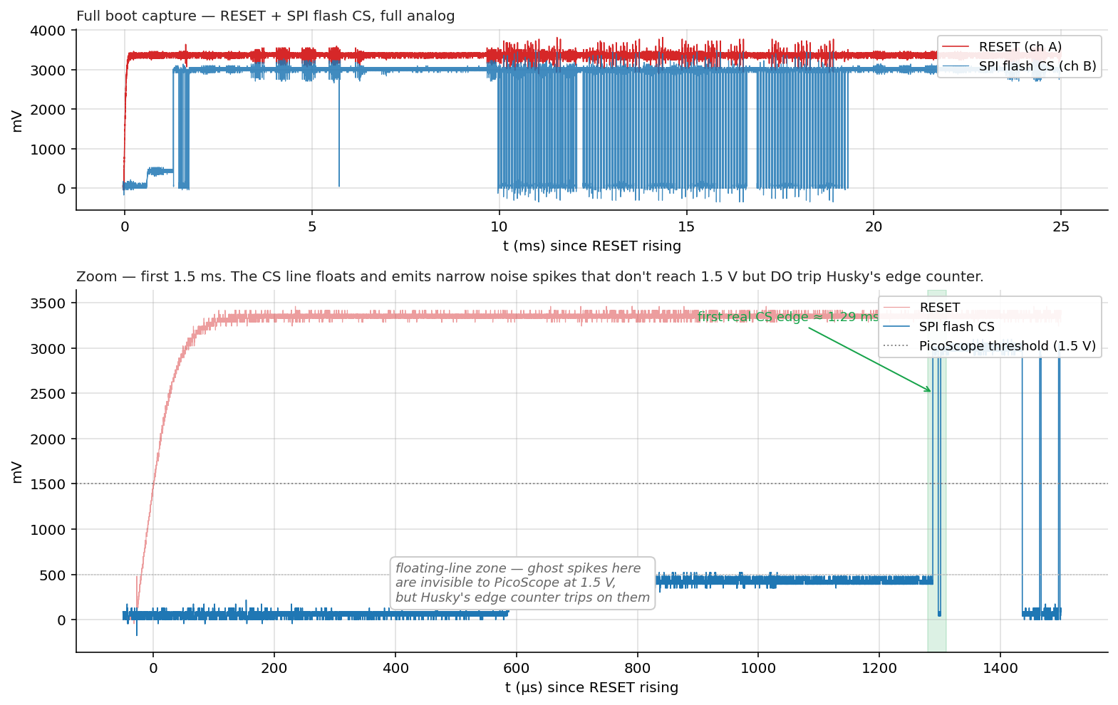
Top: full 25 ms boot capture — RESET (red) and SPI flash CS (blue) in pure analog. Bottom: zoom into the first 1.5 ms. The CS line floats for ~1.3 ms after RESET release, emitting narrow noise spikes — "ghost edges" — that never reach the 1.5 V PicoScope threshold but do trip Husky's TIO4 input. The chip's first real CS edge is at ~1.29 ms (highlighted green band).
Fix is mechanical: wait until the chip is actually driving CS before arming. The host sleeps csdelay_ms = 1.2 ms after releasing RESET, then calls scope.arm() — every edge Husky counts after that is a real flash transaction.
We then used the PicoScope as ground truth to verify the trigger lands where we expect.
Me: “Verify using the picoscope the trigger is at the right location; show me a picture on the wiki.”
With ch C tied to Husky’s MCX glitch-trigger output, we sweep --edges N until the crowbar fires exactly at the last CS edge of the bootloader-load phase (~19.3 ms after RESET release). For our setup that turned out to be --edges 952.
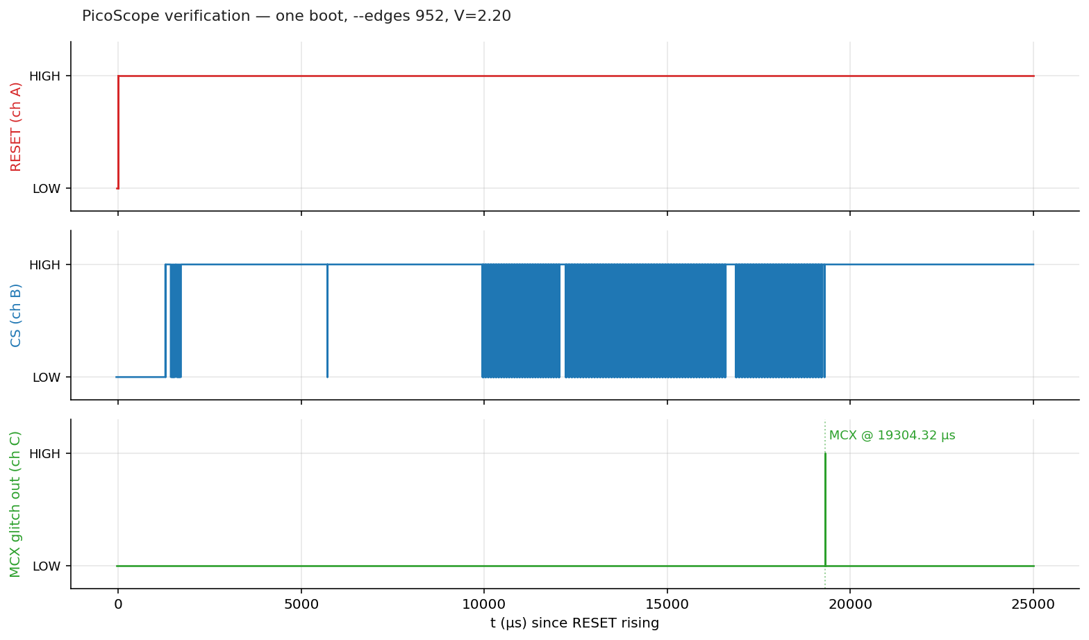
One boot cycle at --edges 952, V=2.20. Top: RESET. Middle: SPI flash CS — bursts from 1.3 ms to ~19.3 ms. Bottom: Husky's MCX glitch-trigger pulse — the dotted line marks the moment the crowbar fires, exactly at the last CS edge of the load phase.
With the anchor verified, the campaign’s --delay and --length flags pick where in the 0–10 µs window after the anchor the glitch fires, and how wide the crowbar pulse is. Everything from here on is a search problem in that two-dimensional space.
Attack flow
Putting all the moving pieces of one glitch attempt on a single timeline:
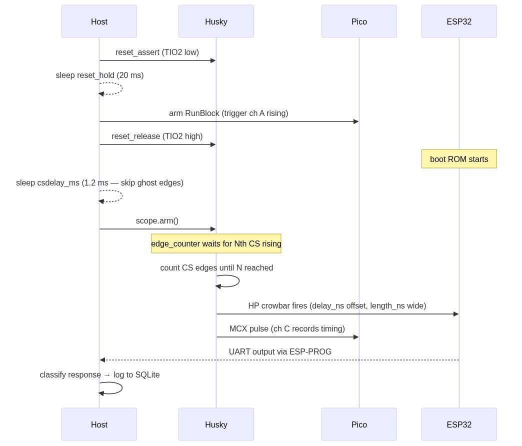
Message sequence for one glitch attempt. The host sleeps 1.2 ms after RESET release before calling scope.arm(), to skip the "ghost edge" zone where the floating CS line inflates Husky's edge counter.
A few details worth pulling out of the diagram:
csdelay_ms = 1.2is the host-side sleep that skips the “ghost edge” zone — the floating SPI flash CS line generates noise spikes that would otherwise inflate Husky’s edge counter.scope.arm()is called as late as possible so the edge counter only sees real CS transitions.scope.capture()at the end of the loop acks the trigger so the next iteration can re-arm. Without this, only the first attempt of a campaign actually fires the crowbar.- The full UART response — raw bytes — is logged to SQLite alongside
delay_ns,length_ns,vset,colorclassification andrun_id. That feeds every dashboard, scatter, heatmap, and post-hoc analysis in this post.
Campaign 1: Identification
For the very first campaign we leaned on the timing analysis above: the call8 we want to skip sits within the first 10 µs after the last bootloader-load CS edge, and the productive crowbar pulse widths for an ESP32 sit somewhere in the 0–5 µs range. So we scan that whole rectangle randomly, with a --max 1000 budget at V = 2.2 V:
Me: “Run 1000 experiments with voltage set to 2.2; randomize delay between 0 and 10_000; the length between 0 and 5000; keep trigger where it is.”
python3 g_HuskyOnly.py \
    --port /dev/ttyUSB2 --csdelay-ms 1.2 \
    --edges 952 --edge-dir rising_edge \
    --delay 0 10000 --length 0 5000 \
    --vset 2.20 \
    --max 1000 \
    --campaign-id "first-1k-2v2" \
    --campaign-name "First 1000-shot at V=2.2 V — random in 10 µs × 5 µs window"
A thousand attempts at ~4 / s is roughly four minutes of wall-clock time. Pointing the glitch monitor at the campaign produced a clear pattern almost immediately. The next three plots all share the same axis (delay 0–10 µs × length 0–5 µs at V = 2.2 V) — what changes is where we sample from, narrowing in on the densest region.
Step 1 — broad scan. Random uniform delay 0–10 µs × length 0–5 µs:
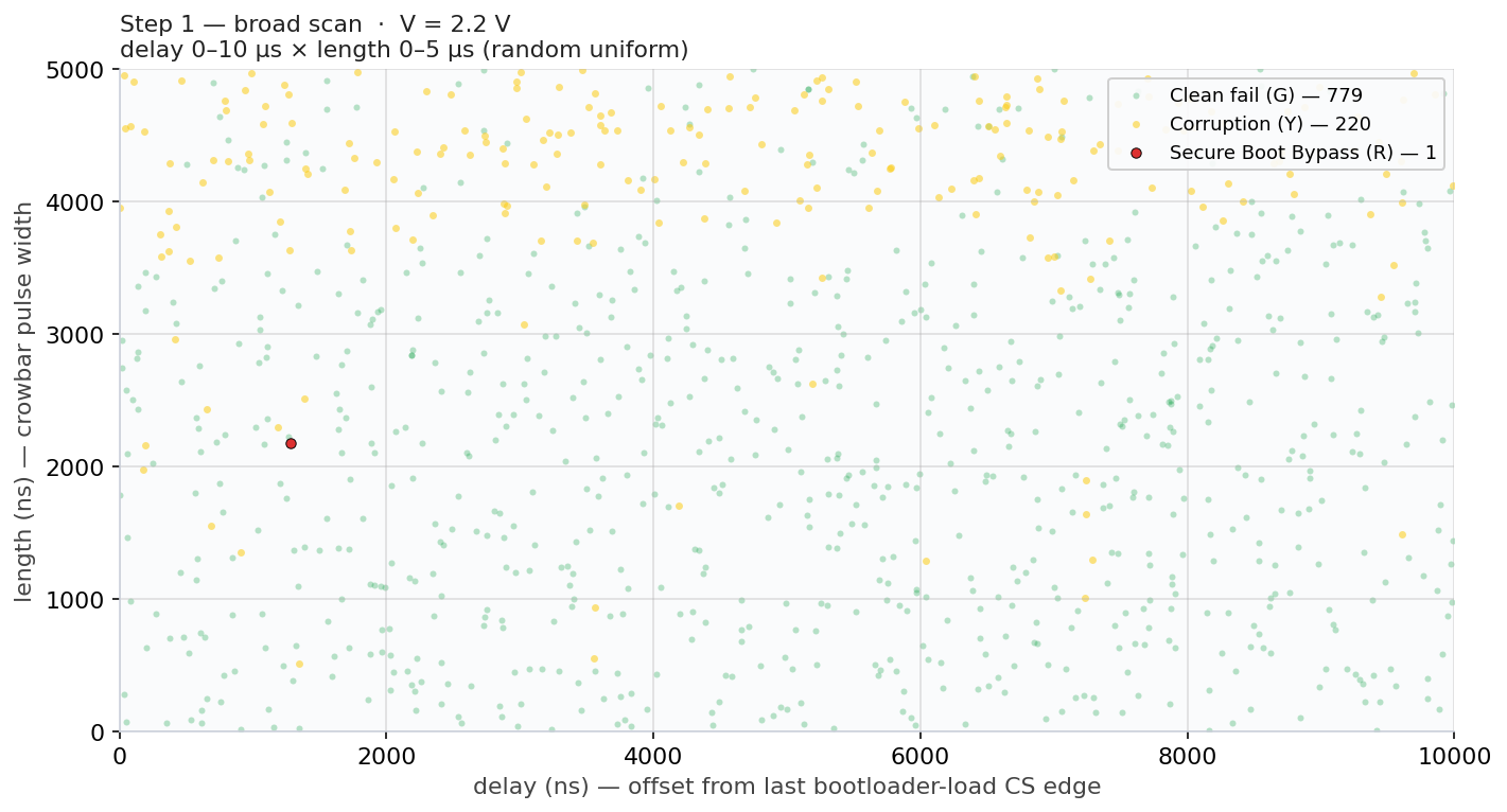
1 000 attempts at V = 2.2 V. Just 1 R hit (0.1 %) — the broad scan barely finds the productive zone, but the corruption (Y) cluster in the upper band hints where to narrow next.
Step 2 — narrowed to the productive band. Now we trim the dead zones identified in Step 1:
Me: “Re-run 1000 experiments at V=2.2 V; narrow to delay 0 to 5000; length 2500 ns to 4000 ns.”
python3 g_HuskyOnly.py \
    --port /dev/ttyUSB2 --csdelay-ms 1.2 \
    --edges 952 --edge-dir rising_edge \
    --delay 0 5000 --length 2500 4000 \
    --vset 2.20 \
    --max 1000 \
    --campaign-id "zoom_step2_mid" \
    --campaign-name "Campaign 1 zoom step 2 — productive band"
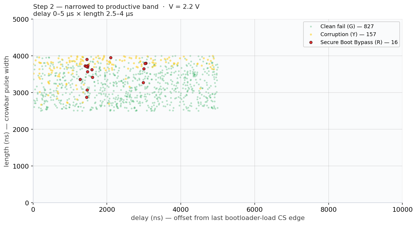
1 000 attempts at V = 2.2 V, narrowed to the band identified in Step 1. R count jumps from 1 to 16 (1.6 %) — a 16× improvement just by trimming the dead zones. The R hits cluster around delay 1–2 µs × length 3–4 µs.
Step 3 — locked into the hot region. One last narrowing onto the tight cluster from Step 2:
Me: “Fix 1000 experiments at V=2.2 V; narrow to delay 1000 to 2000; length 3000 ns to 4000 ns.”
python3 g_HuskyOnly.py \
    --port /dev/ttyUSB2 --csdelay-ms 1.2 \
    --edges 952 --edge-dir rising_edge \
    --delay 1000 2000 --length 3000 4000 \
    --vset 2.20 \
    --max 1000 \
    --campaign-id "zoom_step3_tight" \
    --campaign-name "Campaign 1 zoom step 3 — hot region"
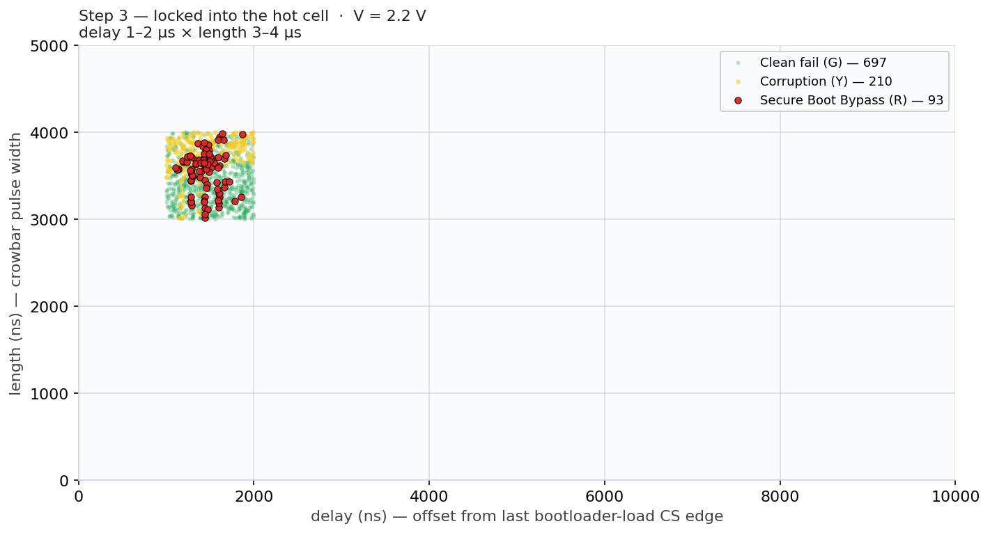
1 000 attempts at V = 2.2 V locked into delay 1–2 µs × length 3–4 µs. R count climbs to 93 (9.3 %) — another ~6× over Step 2. Every red dot is a successful Secure Boot bypass; the call8 we want to skip lives at delay ≈ 1.5 µs and our pulse hits it reliably.
Multiple moments of success. Looking back at Step 2’s data (delay 0–5 µs × length 2.5–4 µs), the R hits don’t cluster around a single point — they form two visible delay bands:
- a dense band around delay ≈ 1.3–1.7 µs, where Step 3 spent most of its budget;
- a smaller second band around delay ≈ 3.0 µs, with R hits at delay 2.97 / 2.99 / 3.03 / 3.05 µs.
That’s not what you’d expect if the attack were skip or corrupt a single instruction. It’s what you’d expect if the crowbar is corrupting different operations inside ets_secure_boot_check_finish(). This gives substance to our hypothesis that any glitch affecting this function results in a successful bypass of Secure Boot.
Campaign 2: Maximize success rate
With the productive zone pinned to delay 1.5–2 µs × length 3–4 µs, the next step was to fix the (delay, length) random window onto its centre and sweep voltage instead. The goal of this campaign was to explore the maximum possible success rate.
Me: “Fix the delay and length and sweep the voltage from 2.0V to 3.0V in 0.01 V steps, 200 experiments per voltage; plot bypass rate vs voltage.”
That’s a fine voltage scan — 20k attempts total:
python3 voltage_fine_scan.py \
    --vmin 2.00 --vmax 3.00 --vstep 0.01 \
    --delay 1500 1600 --length 3400 3500 \
    --experiments 200 \
    --campaign-id "vscan_full_2v_3v"
The result was the most surprising plot of the whole project:
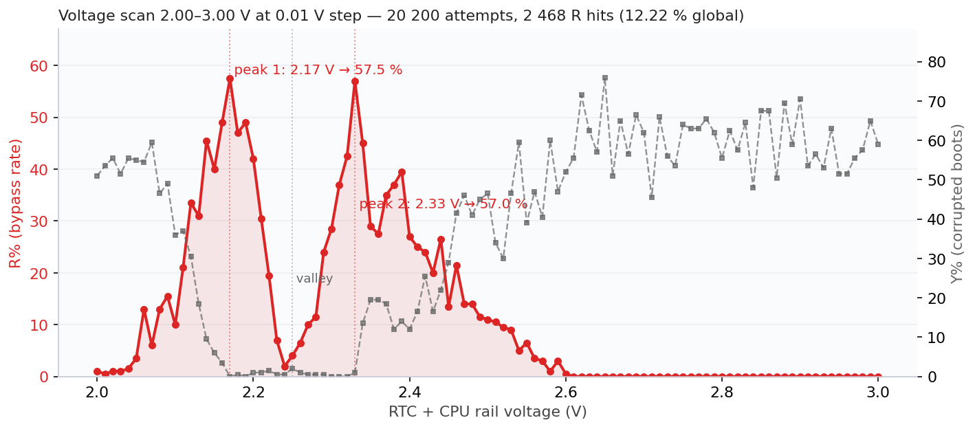
Bypass rate vs RTC+CPU rail voltage at the hot-region parameters. Two sharp peaks — 2.17 V (57.5 %) and 2.33 V (57.0 %) — with a glitch-resistant valley at 2.25 V where the chip flat-out refuses to misbehave.
Two peaks, both producing >57 % success rate. 2 468 successful Secure Boot bypasses out of 20 200 attempts. Moreover, a 12.2 % global success rate that makes the original 0.1 % from earlier look quaint.
Statistics do not lie, but, we have no good explanation yet for this two-peak behavior. This effect can be caused by the internal LDO or the fact that two instructions that are reasonable close to each other, cause the same effect.
Caveats and reflections
What we don’t claim. This is not “AI invented an attack.” The Secure Boot bypass mechanism, glitching the bnei or its operands, was already well-known in the public literature. What we do claim is that, given a goal and a setup, Claude carried out the full engineering loop end-to-end: code, debug, sweep, analyze, refactor, document. All these steps are often only performed by more-experienced Fault Injection practitioners (i.e., doing more than just glitch and pray). Moreover, it did all of this in little time, without getting tired.
We’re not claiming this scales to a novel attack class that does not exist yet. We’re claiming it scales to operationalizing existing FI knowledge in a (very) accessible manner. It will likely enable a larger crowd to perform powerful attacks which require adequate tooling and reasoning.
What this means for the field. A few thoughts, in no particular order:
- Skill compression matters. The AI doesn’t replace expertise, it shrinks the iteration time between hypothesis and result. The cycle from “I wonder if X helps” to “X helps by 12 %” went from a Wednesday to fifteen minutes.
- Tooling is the bottleneck the AI removes. Every campaign that “would have been nice to do but takes too long to instrument” is now cheap. The 0.01-voltage × 200-experiment sweep may have taken days of our time to write, run, and analyze; tonight it cost ten minutes of conversation and two hours of setup time.
- Defensive implications. Hardware FI tooling became more accessible during the last decade. The same now holds up for rich software for interfacing with this hardware tooling. Anyone with great ideas can create great tools without effort.
- What a human still does. Strategic framing, knowing when the data tells you something the AI would gloss over, deciding when to stop, deciding what new attack to attempt next. The interesting parts.
What all of this means for us; we simply do not know! 🤷
- Raelize.