We arrived at the last post about our Fault Injection research on the ESP32. Please read our previous posts as it provides context to the results described in this post.
- Espressif ESP32: Bypassing Secure Boot using EMFI
- Espressif ESP32: Controlling PC during Secure Boot
- Espressif ESP32: Bypassing Flash Encryption (CVE-2020-15048)
During our Fault Injection research on the ESP32, we gradually took steps forward in order to identify the required vulnerabilities that allowed us to bypass Secure Boot and Flash Encryption with a single EM glitch. Moreover, we did not only achieve code execution, we also extracted the plain-text flash data from the chip.
Espressif requested a CVE for the attack described in this post: CVE-2020-13629. Please note, that the attack as described in this post, is only applicable to ESP32 silicon revision 0 and 1. The newer ESP32 V3 silicon supports functionality to disable the UART bootloader that we leveraged for the attack.
UART bootloader
The ESP32 implements an UART bootloader in its ROM code. This feature allows, among other functionality, to program the external flash. It's not uncommon that such functionality is implemented in the ROM code as it's quite robust as the code cannot get corrupt easily. If this functionality would be implemented by code stored in the external flash, any corruption of the flash may result in a bricked device.
Typically, this type of functionality is accessed by booting the chip in a special boot mode. The boot mode selection is often done using one or more external strap pin(s) which are set before resetting the chip. On the ESP32 it works exactly like this pin G0 which is exposed externally.
The UART bootloader supports many interesting commands that can be used to read/write memory, read/write registers and even execute a stub from SRAM.
Executing arbitrary code
The UART bootloader supports loading and executing arbitrary code using the load_ram command. The ESP32's SDK includes all the tooling required to compile the code that can be executed from SRAM. For example, the following code snippet will print SRAM CODE\n on the serial interface.
void __attribute__((noreturn)) call_start_cpu0()
{
    ets_printf("SRAM CODE\n");
    while (1);
}
The esptool.py tool, which is part of the ESP32's SDK, can be used to load the compiled binary into the SRAM after which it will be executed.
esptool.py --chip esp32 --no-stub --port COM3 load_ram code.bin
Interestingly, the UART bootloader cannot disabled and therefore always accessible, even when Secure Boot and Flash Encryption are enabled.
Additional measures
Obviously, if no additional security measures would be taken, leaving the UART bootloader always accessible would render Secure Boot and Flash Encryption likely useless. Therefore, Espressif implemented additional security measures which are enabled using dedicated eFuses.
These are security configuration bits implemented in special memory, often referred to as OTP memory, which can typically only change from 0 to 1. This guarantees, that once enabled, is enabled forever. The following OTP memory bits are used to disable specific functionality when the ESP32 is in the UART bootloader boot mode.
- DISABLE_DL_ENCRYPT: disables flash encryption operation
- DISABLE_DL_DECRYPT: disables transparent flash decryption
- DISABLE_DL_CACHE: disables the entire MMU flash cache
The most relevant OTP memory bit is DISABLE_DL_DECRYPT as it disables the transparent decryption of the flash data.
If not set, it would be possible to simply access the plain-text flash data while the ESP32 is in its UART bootloader boot mode.
If set, any access to the flash, when the chip is in UART bootloader boot mode, will yield just the encrypted data. The Flash Encryption feature, which is fully implemented in hardware and transparent to the processor, is only enabled in when the ESP32 is in Normal boot mode.
The attacks described in this post have all these bits set to 1.
Persistent data in SRAM
The SRAM memory that's used by the ESP32 is typical technology that's used by many chips. It's commonly used to the ROM's stack and executing the first bootloader from flash. It's convenient to use at early boot as it typically require no configuration before it can be used.
We know from previous experience that the data stored in SRAM memory is persistent until it's overwritten or the required power is removed from the physical cells. After a cold reset (i.e. power-cycle) of the chip, the SRAM will be reset to its default state. This often semi-random and unique per chip as the default value for each bit (i.e. 0 or 1) is different.
However, after a warm reset, where the entire chip is reset without removing the power, it may happen that the data stored in SRAM remains unaffected. This persistence of the data is visualized in the picture below.
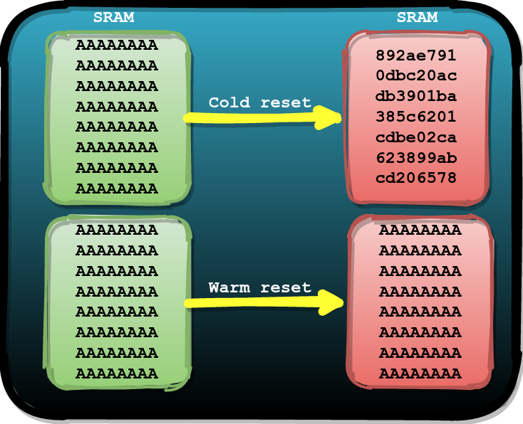
We decided to figure out if this behavior holds up for the ESP32 as well. We identified that the hardware watchdog can be used to issue a warm reset from software. This watchdog can also be issued when the chip is in UART bootloader boot mode and therefore we can use it to reset the ESP32 back into Normal boot mode.
Using some test code, loaded and executed in SRAM using the UART bootloader, we determined that the data in SRAM is indeed persistent after issuing a warm reset using the watchdog. Effectively this means we can boot the ESP32 in Normal boot mode with the SRAM filled with controlled data.
But… how can we (ab)use this?
Road to failure
We envisioned that we may be able to leverage the persistence of data in SRAM across warm resets for an attack. The first attack we came up with is to fill the SRAM with code using the UART bootloader and issue a warm reset using the watchdog. Then, we inject a glitch while the ROM code is overwriting this code with the flash bootloader during a normal boot.
We got this ideas as during our previous experiments, where we turned data transfers into code execution, we noticed that for some experiments the chip started executing from the entry address before the bootloader was finished copying.
Sometimes you just need to try it…
Attack code
The code that we load into the SRAM using the UART bootloader is shown below.
#define a "addi a6, a6, 1;"
#define t a a a a a a a a a a
#define h t t t t t t t t t t
#define d h h h h h h h h h h

void __attribute__((noreturn)) call_start_cpu0() {
    uint8_t cmd;

    ets_printf("SRAM CODE\n");

    while (1) {

        cmd = 0;
        uart_rx_one_char(&cmd);

        if(cmd == 'A') {                                    // 1
            *(unsigned int *)(0x3ff4808c) = 0x4001f880;
            *(unsigned int *)(0x3ff48090) = 0x00003a98;
            *(unsigned int *)(0x3ff4808c) = 0xc001f880;
        }
    }

    asm volatile ( d );                                     // 2

    "movi a6, 0x40; slli a6, a6, 24;"                       // 3
    "movi a7, 0x00; slli a7, a7, 16;"
    "xor a6, a6, a7;"
    "movi a7, 0x7c; slli a7, a7, 8;"
    "xor a6, a6, a7;"
    "movi a7, 0xf8;"
    "xor a6, a6, a7;"

    "movi a10, 0x52; callx8  a6;" // R
    "movi a10, 0x61; callx8  a6;" // a
    "movi a10, 0x65; callx8  a6;" // e
    "movi a10, 0x6C; callx8  a6;" // l
    "movi a10, 0x69; callx8  a6;" // i
    "movi a10, 0x7A; callx8  a6;" // z
    "movi a10, 0x65; callx8  a6;" // e
    "movi a10, 0x21; callx8  a6;" // !
    "movi a10, 0x0a; callx8  a6;" // \n

    while(1);
}
To summarize, the above code implements the following:
- Command handler with a single command to perform a watchdog reset
- NOP-like padding using
addiinstructions - Assembly for printing
Raelize!on the serial interface
Please note, the listing's numbers match the numbers in the code.
Timing
We target a reasonably small attack window at the start of F which is shown in the picture below. We know from previous experiments that during this moment the flash bootloader is copied.
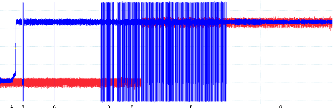
The glitch must be injected before our code in SRAM is entirely overwritten by the valid flash bootloader.
Attack cycle
We took the following steps for each experiment to determine if the attack idea actually works. A successful glitch will print Raelize! on the serial interface.
- Set pin G0 to low and perform a cold reset to enter UART bootloader boot mode
- Use the
load_ramcommand to execute our attack code from SRAM - Send an
Ato the program to issue a warm reset into normal boot mode - Inject a glitch while the flash bootloader is being copied by the ROM code
Results
After running these experiments for more than a day, resulting in more than 1 million experiments, we did not observe any successful glitch…
An unexpected result
Nonetheless, while analyzing the results, we noticed something unexpected.
The serial interface output for one of the experiments, which is shown below, indicated that the glitch caused an illegal instruction exception.
ets Jun  8 2016 00:22:57
rst:0x10 (RTCWDT_RTC_RESET),boot:0x13 (SPI_FAST_FLASH_BOOT)
configsip: 0, SPIWP:0xee
clk_drv:0x00,q_drv:0x00,d_drv:0x00,cs0_drv:0x00,hd_drv:0x00,wp_drv:0x00
mode:DIO, clock div:2
load:0x3fff0008,len:4
load:0x3fff000c,len:3220
load:0x40078000,len:4816
load:0x40080400,len:18640
entry 0x40080740
Fatal exception (0): IllegalInstruction
epc1=0x661b661b, epc2=0x00000000, epc3=0x00000000,
excvaddr=0x00000000, depc=0x00000000
These type of exceptions happened quite often when glitches are injected in a chip. This was not different for the ESP32. For most the exceptions the PC register is set to a value that's expected (i.e. a valid address). It does not happen often the PC register is set to such an interesting value.
The Illegal Instruction exception is caused as there is no valid instruction stored at the 0x661b661b address. We conclude this value must come from somewhere and that is cannot magically end up in the PC register.
We analyzed the code that we load into the SRAM in order to find an explanation. The binary code, of which a snippet is shown below, quickly gave us the answer we were looking for. The value 0x661b661b is easily identified in the above binary image. It actually represents two addi a6, a6, 1 instructions of which we implemented 1000 in our test code.
00000000  e9 02 02 10 28 04 08 40  ee 00 00 00 00 00 00 00  |....(..@........|
00000010  00 00 00 00 00 00 00 01  00 00 ff 3f 0c 00 00 00  |...........?....|
00000020  53 52 41 4d 20 43 4f 44  45 0a 00 00 00 04 08 40  |SRAM CODE......@|
00000030  50 09 00 00 00 00 ff 3f  04 04 fe 3f 4d 04 08 40  |P......?...?M..@|
00000040  00 04 fe 3f 8c 80 f4 3f  90 80 f4 3f 98 3a 00 00  |...?...?...?.:..|
00000050  80 f8 01 c0 54 7d 00 40  d0 92 00 40 36 61 00 a1  |....T}.@...@6a..|
00000060  f5 ff 81 fc ff e0 08 00  0c 08 82 41 00 ad 01 81  |...........A....|
00000070  fa ff e0 08 00 82 01 00  4c 19 97 98 1f 81 ef ff  |........L.......|
00000080  91 ee ff 89 09 91 ee ff  89 09 91 f0 ff 81 ee ff  |................|
00000090  99 08 91 ef ff 81 eb ff  99 08 86 f2 ff 5c a9 97  |.............\..|
000000a0  98 c5 1b 66 1b 66 1b 66  1b 66 1b 66 1b 66 3e 0c  |...f.f.f.f.f.f>.|
000000b0  1b 66 1b 66 1b 66 1b 66  1b 66 1b 66 1b 66 1b 66  |.f.f.f.f.f.f.f.f|
000000c0  1b 66 1b 66 1b 66 1b 66  1b 66 1b 66 1b 66 1b 66  |.f.f.f.f.f.f.f.f|
000000d0  1b 66 1b 66 1b 66 1b 66  1b 66 1b 66 1b 66 1b 66  |.f.f.f.f.f.f.f.f|
...
00000330  1b 66 1b 66 1b 66 1b 66  1b 66 1b 66 1b 66 1b 66  |.f.f.f.f.f.f.f.f|
00000340  1b 66 1b 66 1b 66 1b 66  1b 66 1b 66 1b 66 1b 66  |.f.f.f.f.f.f.f.f|
00000350  1b 66 1b 66 1b 66 1b 66  1b 66 1b 66 1b 66 1b 66  |.f.f.f.f.f.f.f.f|
We just use these instructions as NOPs in order to create a landing zone in a similar fashion a NOP-sled is often used in software exploits. We did not anticipate these instructions would end up in the PC register.
Of course, we did not mind either. We concluded that, we are able to load data from SRAM into the PC register when we inject a glitch while the flash bootloader is being copied by the ROM code .
We quickly realized, we now have all the ingredients to cook up an attack where we bypass Secure Boot and Flash Encryption using a single glitch. We reused some of the knowledge obtained during a previously described attack where we take control of the PC register.
Road to success
We reused most of the code that we previously loaded into SRAM using the UART bootloader. Only the payload (i.e. printing) that we intended to execute is removed as our strategy is now to set the PC register to an arbitrary value in order to take control.
#define a "addi a6, a6, 1;"
#define t a a a a a a a a a a
#define h t t t t t t t t t t
#define d h h h h h h h h h h

void __attribute__((noreturn)) call_start_cpu0() {
    uint8_t cmd;

    ets_printf("SRAM CODE\n");

    while (1) {

        cmd = 0;
        uart_rx_one_char(&cmd);

        if(cmd == 'A') {
            *(unsigned int *)(0x3ff4808c) = 0x4001f880;
            *(unsigned int *)(0x3ff48090) = 0x00003a98;
            *(unsigned int *)(0x3ff4808c) = 0xc001f880;
        }
    }

    asm volatile ( d );

    while(1);
}
After compiling the above code, we overwrite directly in the binary the addi instructions with the address pointer 0x4005a980. This address points to a function in the ROM code that prints something on the serial interface. This allows us to identify when we are successful.
We fixed the glitch parameters to that of the experiment that caused the Illegal Instruction exception. After a short while, we successfully identified several experiments during which the address pointer is loaded into the PC register. Effectively this provides us with control of the PC register and we can likely achieve arbitrary code execution.
Why does this work?
Good question. Not so easy to answer.
Unfortunately, we do not have a sound answer for you. We definitely did not anticipate that controlling the data at the destination could yield control of the PC register. We came up with a few possibilities, but we cannot say with full confidence if any of these is actually correct.
One explanation is that the glitch may corrupt both operands of the ldr instruction in order to load a value from the destination into the a0. This is similar as the previously described attack where we control PC indirectly by controlling the source data.
Moreover, it's a possibility that the ROM code implements functionality that facilitates this attack. In other words, we may execute valid code within the ROM due to our glitch that causes the value from SRAM to be loaded into the PC register.
More thorough investigation is required in order to determine what exactly allows us to perform this attack. However, from an attacker's perspective, it's sufficient to realize how to get control of PC in order to build the exploit.
Extracting plain-text data
Even though we have control of the PC register, we are not yet able to extract the plain-text data from the flash. We decided to leverage the UART bootloader functionality to do so.
We decided to jump directly to the UART bootloader while the chip is in Normal boot mode. For this attack we overwrite the addi instructions in the code that we load into SRAM with address pointers to the start of the UART bootloader (0x0x40007a19).
The UART bootloader prints a string on the serial interface which is shown below. We can use this to identify if we are successful or not.
waiting for download\n"
Once we observe a successful experiment, we can simply use the esptool.py to issue a read_mem command in order to access plain-text flash data. The command below reads 4 bytes from the address where the external flash is mapped (0x3f400000).
esptool.py --no-stub --before no_reset --after no_reset read_mem 0x3f400000
Unfortunately, this did not work. For some reason the processor is replying with 0xbad00bad which is an indication we read from an unmapped page.
esptool.py v2.8
Serial port COM8
Connecting....
Detecting chip type... ESP32
Chip is ESP32D0WDQ6 (revision 1)
Crystal is 40MHz
MAC: 24:6f:28:24:75:08
Enabling default SPI flash mode...
0x3f400000 = 0xbad00bad
Staying in bootloader.
We noticed that there is quite some configuration done at the start of the UART bootloader. We assume it may affect the MMU as well.
Just to try something different, we decided to jump directly to the command handler of the UART bootloader itself (0x40007a4e). Once in the hander, we can send a raw read_mem command directly on the serial interface which is shown below.
target.write(b'\xc0\x00\x0a\x04\x00\x00\x00\x00\x00\x00\x00\x40\x3f\xc0')
Unfortunately, by jumping directly to the handler, the string that's printed (i.e. waiting for download\n") is not printed anymore. Therefore, we cannot easily identify successful experiments. Therefore, we decided to simply always send the command, regardless if we are successful or not. We used a very short serial interface timeout in order to minimize the overhead of almost always hitting the timeout.
After a short while, we observed the first successful experiments!
Conclusion
In this post we described an attack on the ESP32 where we bypass its Secure Boot and Flash Encryption features using a single EM glitch. Moreover, we leveraged the vulnerability exploited by this attack to extract the plain-text data from the encrypted flash.
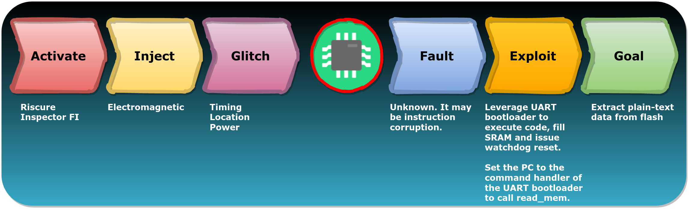
We can use FIRM to break down the attack in multiple comprehensible stages.
Interestingly, two weaknesses of the ESP32 facilitated this attack. First, the UART bootloader cannot be disabled and is always accessible. Second, the data loaded in SRAM is persistent across warm resets and can therefore be filled with arbitrary data using UART bootloader.
Espressif indicated in their advisory related to this attack that newer versions of the ESP32 include functionality to completely disable this feature.
Final thoughts
All standard embedded technologies are vulnerable to Fault Injection attacks. Therefore, it's not surprising at all that the ESP32 is vulnerable as well. These type of chips are simply not made to be resilient against these type of attacks. However, and this is important, this does not mean that these attacks do not impose a risk.
Our research has shown that leveraging chip-level weaknesses for Fault Injection attack is very effective. We have not seen many public examples yet as most attack still focus on traditional approaches where the focus is mostly on bypassing just a check.
We believe the full potential of Fault Injection attacks is still unexplored. Most research until recently focused mostly on the injection method itself (i.e. Activate, Inject and Glitch) compared to what can be accomplished due to a vulnerable chip (i.e. Fault, Exploit and Goal).

We are confident that creative usage of new and undefined fault models, will give rise to unforeseen attacks, where exciting exploitation strategies are used, for a wide variety of different goals.