At the end of 2023, we started analyzing the security of Google’s Nest Wifi Pro. Of course, besides overcoming several physical practicalities (i.e., dumping the flash), this involves a significant amount of software reverse engineering. As likely evident from our previously conducted research, at Raelize, we like to look beyond the software stack. So, in line with our DNA, while reverse engineering the software stack, we decided to test the resilience of the Google Nest Wifi Pro to electromagnetic (EM) glitches as well.
Please note, we have actually discovered several software vulnerabilities, mostly in low-level components running at a high privilege. However, none of these vulnerabilities has surfaced yet in Google (or Qualcomm 😗) monthly security bulletins. Hence, we will have to postpone discussing them to a later time.
In a series of posts, we will discuss a hardware vulnerability that we successfully exploited using EM glitches. Note, this attack was already discussed at at hardwear.io USA 2025 (slides).
- Google Wifi Pro: Glitching from Root to EL3 - Part 1 - Characterization
- Google Wifi Pro: Glitching from Root to EL3 - Part 2 - Arbitrary read/write at EL3
- Google Wifi Pro: Glitching from Root to EL3 - Part 3 - Arbitrary code exec at EL3
In this first post, we will explain how we characterized the Qualcomm’s IPQ5018 SoC to determine its susceptibility towards EM glitches.
We have organized the content in the following sections:
We hope you appreciate this post; have fun! :)
Background
Google’s Nest Wifi Pro is a consumer WiFi router available in many areas of the world. We have identified and exploited the vulnerability on a device running firmware version 3.73.406133, which was the latest available version at the time of our research.
As far as we know, the vulnerability is rooted in hardware and cannot be patched. Also, the code construction that we leveraged for the exploitation remained unchanged in the last released firmware versions. Therefore, the attack described in this post should apply to devices running the latest firmware version.
Note, the characterization test described in this post relies on the ability to execute arbitrary code in Android. We were able to perform it by leveraging a Secure Boot bypass we disclosed to Google. A successful exploit of such a vulnerability gave us a root shell, along with a few other things, including the privileges to modify the init.rc file, which is used to configure Android at early boot.
The proc entry /proc/sys/kernel/modules_disabled governs the loading of Linux kernel modules (LKMs) at runtime. If this Linux Kernel security feature is set to 1, kernel module loading is disabled until the system is rebooted. The value of this specific entry is set to 1 in the init.rc file. Our acquired privileges allowed us to change such setting in init.rc, allowing us to load LKMs at runtime.
The vulnerability (i.e., CVE-2024-22013) that we used to get a root shell and the power to load custom kernel modules was also found by Sergei, which he discussed in more detail in his presentation at Hardwear.io Netherlands 2024.
Characterization
Whenever it’s possible, we like to characterize the susceptibility of a target to a specific fault injection technique (e.g. EM), before commencing to the real attack. This allows us to determine, in a controlled and favorable setting, if the underlying platform can be affected by our glitches. With this characterization step we were able to successfully identify that the Qualcomm’s IPQ5018 SoC is vulnerable to EM glitches.
This vulnerability, being it a hardware vulnerability, cannot be fixed. In an analogy to software exploitation, you could compare the characterization to the identification of a software vulnerability, whose exploitability and impact get demonstrated by actually exploiting it.
Tooling
Keysight’s EM tooling works very similar to all EMFI tooling. A (very) fast rush of current is driven through a coil, generating a spike (i.e. a rapid variation) in the associated electromagnetic field. This induces eddy currents within the chip’s circuits nets, altering transistor’s states and introducing faults in the represented logical values. This may, for instance, allow us to affect CPU operations and corrupt the instructions being executed.
We have been stressing this again and again: considering the skipping of instructions as the only effect of FI attacks, significant limits the exploration of the full potential of FI attacks. Hence, we always think and reason along the lines of corrupting instructions (i.e., changing opcodes and operands) when discussing FI attacks targeting the CPU of a chip.
A full diagram of the setup is shown below. We used Keysight’s DS1180A Glitch Pattern Generator, DS1010A Precision XYZ Stage and DS1120A Unidirectional Fault Injection Probe. Additionally, we used a solid-state relay to control the external power supply of the target, which allowed us to reset the device and bring it to a known state.
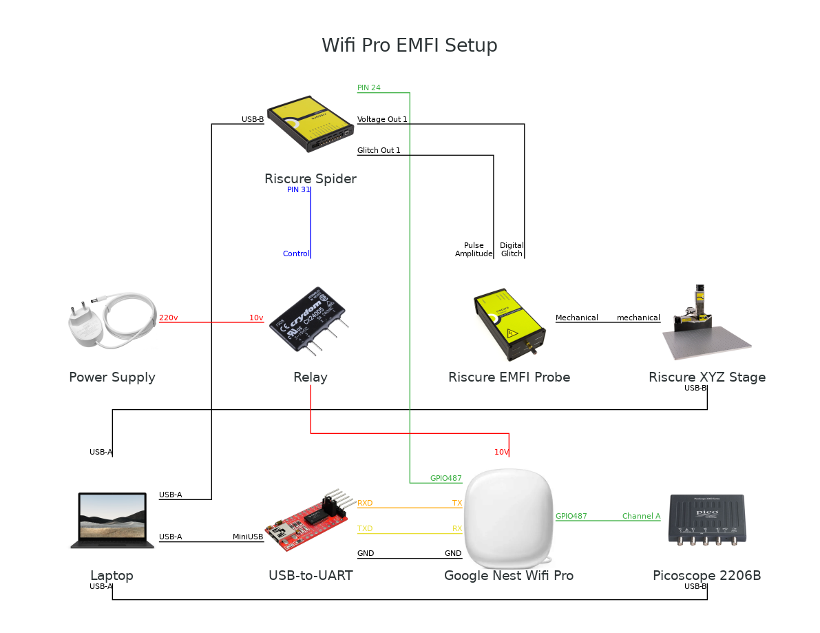
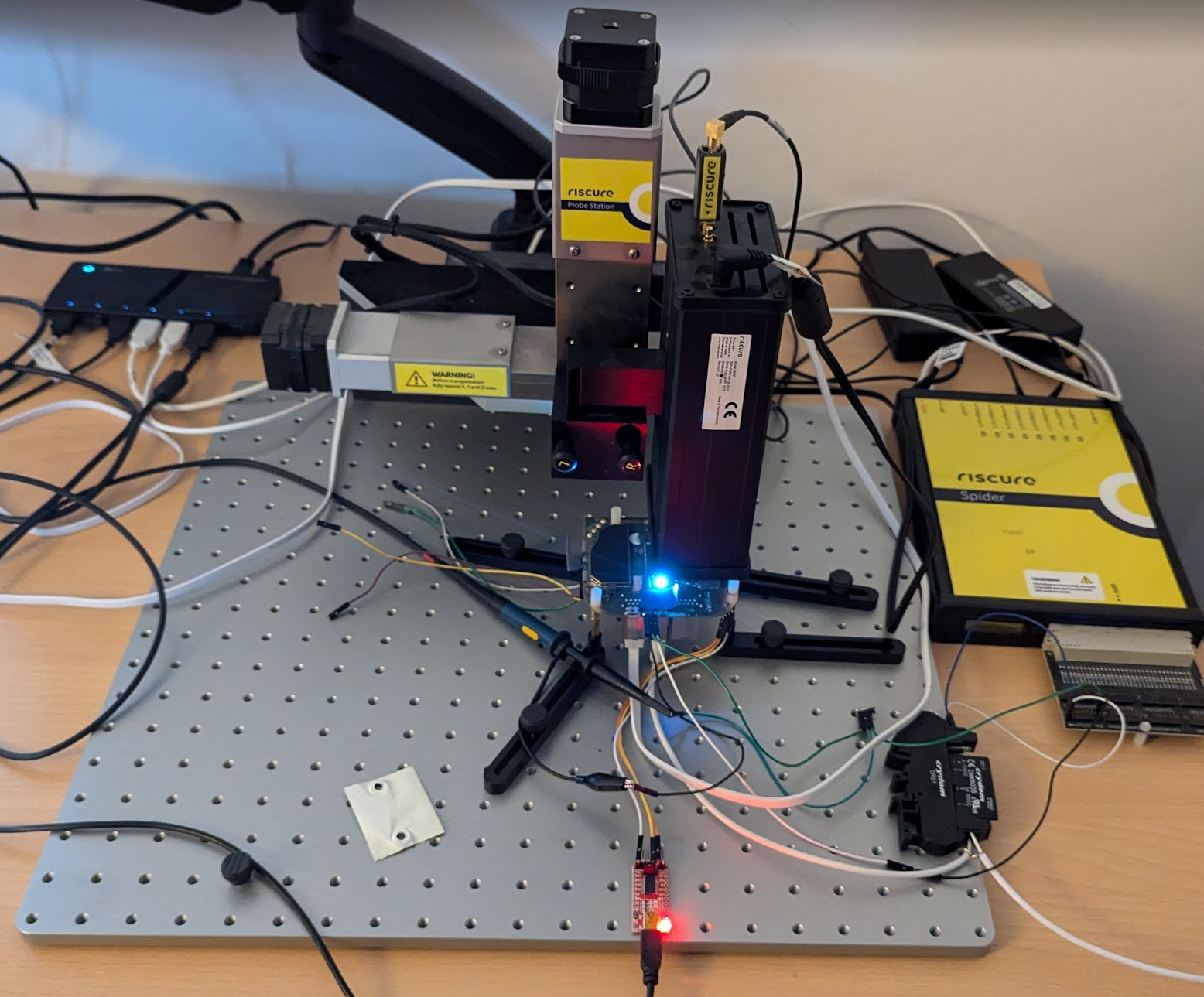
An actual photo of the setup at our lab is shown below.
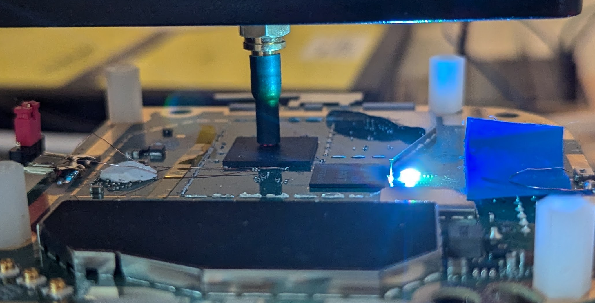
The EMFI probe tip is placed very close to, or even better, touching, the surface of the chip. This is shown in the image below.
Communication
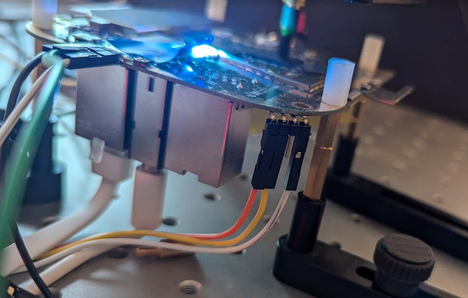
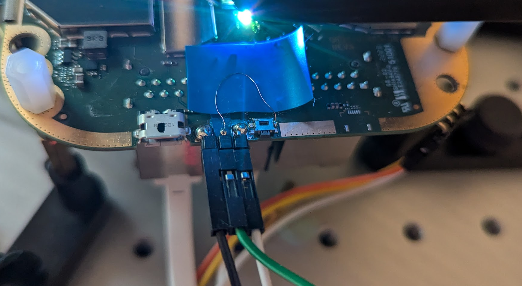
The device exposes a serial interface (i.e., TX and RX) on the PCB. We found these by probing the various test pads on the PCB of the device. The pads that carry the TX and RX signals of the serial interface are shown below.
We use this serial interface to communicate with the test code used for the characterization.
Trigger
Being able to time the glitch is fundamental for FI attacks. For this target, we decided to leverage the GPIO signal used for the factory reset button. We simply soldered a wire to one of the reset button pads in order to access the GPIO signal at our best convenience.
This GPIO is configured in the init.rc at boot (see below).
on init
    Export FDR button GPIO
    write /sys/class/gpio/export "487"
    write /sys/class/gpio/gpio487/active_low "1"
As the GPIO signal is configured as an input pin, we re-configure it as an output pin, by modifying the init.rc. This prevents us from performing a factory reset, but that is likely not something we want to do anyways.
on init
    # Export FDR button GPIO
    # write /sys/class/gpio/export "487"
    # write /sys/class/gpio/gpio487/active_low "1"

    write /sys/class/gpio/export "487"
    write /sys/class/gpio/gpio487/active_low "1"
    write /sys/class/gpio/gpio487/direction "out"
    write /sys/class/gpio/gpio487/value "3"
We confirmed that we can control this GPIO pin using devmem from our root shell.
We can set the GPIO high (i.e., trigger up). This allows us to identify, using an oscilloscope, when the relevant part of our test code starts executing.
/ # devmem 0x01016004 32 0x3
We can also set the GPIO low (i.e., trigger down). This allows us to identify, using an oscilloscope, when the test code has finished executing.
/ # devmem 0x01016004 32 0x0
Now that the address and the values to control the GPIO are known, we can also do this also directly from code (i.e., by simply writing to those addresses).
Reset
When glitches are injected, it’s highly likely that, at some point, the target may enter into an erroneous state. A reliable reset procedure is needed to restore the target to a known state and flawlessly continue with the experiments. We decided to perform a power-on reset, whenever we need to reboot the target, by directly controlling the external power supply.

We use a solid state relay, driven by a GPIO pin from our glitcher, to switch the original power supply on and off.
Characterization test code
The Linux kernel module we used for the characterization implements the code shown below.
#include <linux/module.h>
#include <linux/kernel.h>
#include <linux/types.h>
#include <linux/dma-mapping.h>
#include <asm/cacheflush.h>

MODULE_LICENSE("GPL");
MODULE_AUTHOR("Raelize");
MODULE_DESCRIPTION("CHARACTERIZATION 1 for Google's Nest Wi-Fi Pro (3.73.406133)");
MODULE_VERSION("1.0");

static u32 _command = 0x1;
static u32 _iterations = 0x0;

module_param(_command, uint, S_IRUGO);
module_param(_iterations, uint, S_IRUGO);

#define o "add r7, r7, #1;"
#define t o o o o o o o o o o
#define h t t t t t t t t t t
#define d h h h h h h h h h h
#define x d d d d d d d d d d

static int unrolled_loop(volatile u32 *trigger) {
    volatile u32 counter = 0;

    *trigger = 0x3;

    asm volatile(
        "mov r7, #0;"
        x
        "mov %[counter], r7;"

        : [counter] "=r" (counter)
        :
        : "r7", "r12"
    );

    *trigger = 0x0;

    printk(KERN_ALERT "AAAA%08xBBBB%08xCCCC\n", counter, counter);
    return 0;
}

static int __init characterize_1_init(void) {
    volatile uint32_t *trigger;

    printk(KERN_ALERT "characterize_1 (init)!\n");

    trigger = ioremap(0x01016004, 4);

    if(_command == 1) {
        unrolled_loop(trigger);
    } else {
        printk(KERN_ALERT "characterize_1 (command (%d) unsupported)!\n", _command);
    }
    return 0;
}

static void __exit characterize_1_exit(void) {
    printk(KERN_ALERT "characterize_1 (exit)!\n");
}

module_init(characterize_1_init);
module_exit(characterize_1_exit);
The function characterize_1_init is executed directly after the Linux kernel module is loaded using insmod. The module parameter _command, which is passed when the kernel module is loaded, is used to trigger the execution of the unrolled_loop function. This function implements the following steps:
- Set trigger high by writing
3to0x01016004 - Set register
r7to0 - Increase the
r7with1for10,000times - Set trigger low by writing
0to0x01016004 - Print the value contained in
r7in the kernel log
To determine if Qualcomm’s IPQ5018 SoC is sensitive to EM glitches, we inject the glitch while the counter is being increased using the add instructions. When the glitch results in a fault altering the intended behavior of an add instruction, we expect to see the output counter value different from the expected value (i.e., 10,000).
We can run the kernel module as follows:
# insmod characterize_1.ko _command=1 _iterations=10000 && rmmod characterize_1
[ 1054.149388] characterize_1 (init)!
[ 1054.149491] AAAA00002710BBBB00002710CCCC
[ 1054.176611] characterize_1 (exit)!
In the example above, the counter value is set to 0x2710 in hex (i.e. 10,000 in decimal). Printing the counter value twice allows us to identify responses where the counter has been modified by a communication malfunction. This assures that we do not classify experiments incorrectly.
Timing
We measured the time between the trigger up and down moment using an oscilloscope to get an idea of when to inject the glitch.
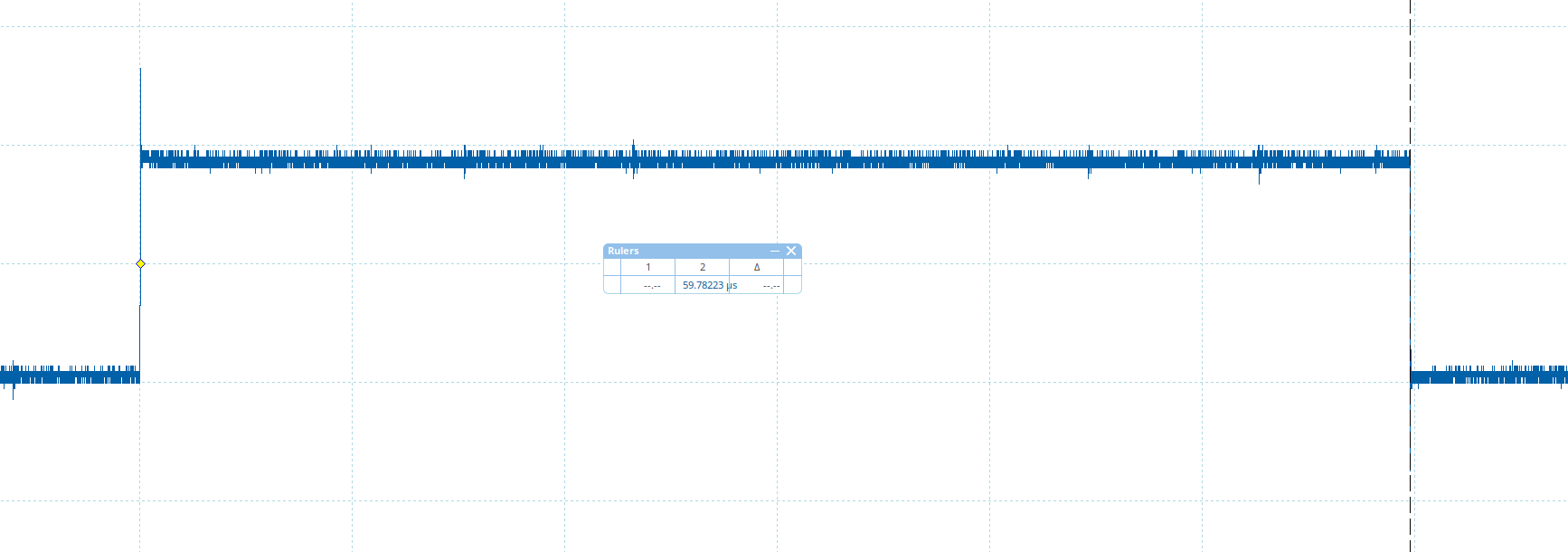
Based on the above timing, we decided to inject our glitch between 20,000 μs and 40,000 μs after the trigger goes up. This ensures that we are injecting glitches only when the add instructions are executed and no surrounding code is hit. Precise timing of our glitch is not too important to determine whether the Qualcomm’s IPQ5018 SoC is vulnerable. It does not matter too much which add instruction we corrupt, as long as we corrupt one.
Boot time
The duration of a single experiment is the biggest disadvantage when characterizing using a kernel module. The kernel module can only be loaded after having booted into the root shell. This takes a significant amount of time due to the booting time, especially when compared to implementing the test code directly in the bootloader (e.g., U-Boot). We expect to reset the target often, so the overhead to boot, has a significant impact on the overall characterization.
We decided to speed up the boot process for an earlier loading of the kernel module. We made the following additions to init.rc at the end of on init, which spawns our root shell very early at boot. This results in a non-functional device, however we confirmed this is sufficient for loading a kernel module.
on init
    ...
    write /sys/devices/system/cpu/cpu0/online "1"
    write /sys/devices/system/cpu/cpu1/online "0"
    exec /factory/raelize/bin/sh
The /factory/raelize/bin/sh is a symlink to a pre-compiled busybox binary we stored on the device. We also made sure that only core 0 (i.e., cpu0) is available at the moment of testing to prevent any possible issues due to scheduling or parallel execution.
Characterization results
We scanned the surface of Qualcomm’s IPQ5018 SoC in a grid of 10 x 10 with Keysight’s EMFI probe. After performing roughly 45 experiments at each location, where we randomize the power of the EM probe between 10% and 100%, we observed several locations where the counter value is different than the expected value.
We plot the experiments using our TAoFI-Analyzer, for which the results are shown below. The red dots represent the locations where we are able to modify the counter value.
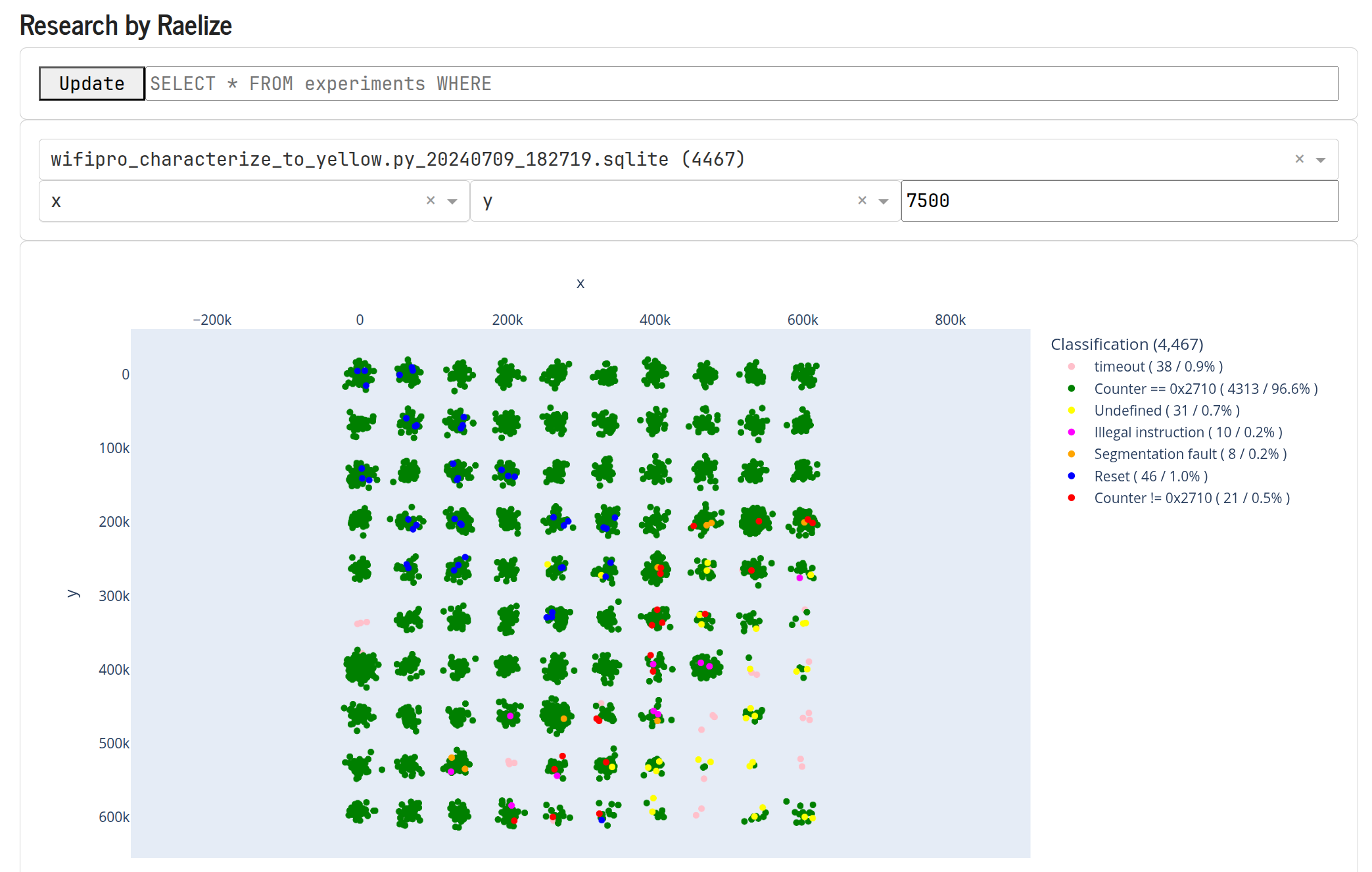
Several of the interesting results are listed below.
| Response | Description |
|---|---|
AAAA00002710BBBB00002710CCCC |
expected (i.e., glitch has no impact) |
AAAA0000270fBBBB0000270fCCCC |
counter - 1 |
AAAA00002790BBBB00002790CCCC |
counter + 0x80 |
AAAA000027c0BBBB000027c0CCCC |
counter + 0xb0 |
AAAA4000198eBBBB4000198eCCCC |
Address in DDR |
AAAA6fb91dacBBBB6fb91dacCCCC |
unknown |
It’s difficult to determine what type of fault exactly materialized as a result of the injected EM glitch. However, seeing a counter value of 0x270f (i.e., counter - 1) is typically a sign that the target is indeed vulnerable, at least in the widely known instruction skipping interpretation. Moreover, seeing DDR addresses end up in the counter is a good indication for instruction corruption as the content of another register (likely) got moved into the register used for the counter (i.e., we corrupted an operand of the add instruction).
To increase our chances for success, we decided to fix the EM probe on a location where we were able to change the counter value to 0x270f (i.e., counter - 1). Moving the probe across the surface of the Qualcomm’s IPQ5018 SoC is a time consuming process. Therefore, by fixing the probe, we can more efficiently search the glitch parameters’ space (i.e., location, timing and power).
Conclusion
We successfully determined Qualcomm’s IPQ5018 SoC is susceptible to EM glitches. We determined this by running characterization code in a custom Linux kernel module. Identifying a vulnerable location is fairly simple and can be done within hours.
The results of the characterization test gave us good confidence we can alter the intended behavior of the instructions executed by the CPU. Given that the Secure Monitor code is executed by the same CPU and the code we executed is not specific to a Non-Secure operation mode (i.e. REE), we felt confident that Secure Monitor code execution could be also affected by EM glitches.
We decided to move forward with performing an attack on the Secure Monitor (EL3) and this adventure is described in more detail in the next post of this series of posts.
Ending
Feel free to reach out for questions or remarks related to this research. As always, we are available to give training on the research we perform, during which you will gain hands-on experience exploiting the vulnerabilities described in this post.
- Raelize.