Our research during the last few years definitely points out our interest in Fault Injection (FI) attacks. We produced numerous publications, which we presented at both academic and security conferences. Among other research, we showed that FI is an effective technique for for bypassing Secure Boot (2016, 2019 and 2019) and escalating privileges on Linux (2017, 2017 and 2017).
Like many of you, our curiosity is constantly sparked and therefore we cannot prevent ourselves from injecting glitches. This post will be your first peek into our new and exciting FI research.
Our research (2016-2019)
Our presentation at POC2019 advances and generalizes the research we published in 2016 at FDTC, where we showed that “data transfers” can yield “arbitrary code execution” using FI. During our demonstration live on stage we injected voltage glitches into the Espressif ESP32 using the open source iceGLITCH. More specifically, we showed how FI can be used to modify callx8 instructions in order to achieve arbitrary control of the program counter in situations where the attacker controls nothing more than just the data being transferred.
It's important to point out that our 2016 research showed the program counter can be be controlled on processor architectures where it is directly addressable (e.g. ARMv7). Our 2019 research showed that the program counter can be controlled even if the it is not directly addressable (e.g. ARMv8). Moreover, maybe even more relevant, this is possible leveraging common software constructs such as the memcpy function.
Let us be clear…
You can perform these type of attack when you only control the data being transferred. Neither the destination nor the source of the data transfer needs to be controlled, just the data itself. Moreover, you can leverage common software constructs executed by privileged code (e.g. Kernel) that copy data from an untrusted domain (e.g. an communication interface or external data source like flash), which are present on any device. Then, if the underlying hardware is vulnerable to FI, and many standard chips are, you can achieve full control of the program counter, regardless of the processor architecture.
We disclosed our research to Espressif before the presentation. It was received with interest and we discussed the potential risk for the ESP32 chip. Nonetheless, as the results were achieved in a fully controlled environment targeting test code, we agreed that the impact was minimal at the time.
Our research (2020 and beyond)
Fast forward to early 2020 and we obtained new hardware FI tooling to support our research endeavors. We decided to test our new capabilities on a target already available to us and that we were familiar with. We decided to focus on injecting electromagnetic (EM) glitches. We will refer to this technique as EMFI.
We started with a typical approach where we target test code that is entirely under our control in order to determine the resilience of the ESP32 towards EM glitches. Once we determined the ESP32 is vulnerable, we set our final goal to put our 2019 research into practice.
We decided our first step towards to this goal was to bypass the Secure Boot implementation of the ESP32. It's important to point out that when we started our research, several researchers already published FI attacks on this implementation for which Espressif issued an advisory. Differently from the attacks already published, we used EM glitches instead of voltage glitches to trigger a similar hardware vulnerability. Our approach has several advantages, as EMFI:
- typically requires no invasive modifications to the target
- is somewhat localized, as the EM field has a definite spatial distribution
Interestingly, besides reproducing the already published attack, we identified several new approaches for exploiting the faults we introduce, which allow us to bypass both Secure Boot and Flash Encryption. By doing so, we also identified several new vulnerabilities for which Espressif issued an advisory. Espressif indicated that these attacks do not apply to the updated ESP32 V3 and ESP32-S2 chips.
In this post we describe our approach for bypassing Secure Boot without Flash Encryption enabled (i.e. reproducing CVE-2019-15894) using EMFI. In several upcoming posts, which will be posted in the upcoming weeks, we will describe our other attacks, including the new vulnerabilities we identified (i.e. CVE-2020-15048 and CVE-2020-13629).
Setup
After over a decade of conducting FI testing and research, we know out of firsthand experience that the identification and exploitation of FI vulnerabilities may require a long breath. It's not always so trivial as some may make you believe. Expert tooling in the hands of advanced users, can make a dramatic difference in the identification phase, let alone during the exploitation of the identified vulnerabilities. Therefore, we like to use commercially available tooling during our FI research.
We believe that our results may be achieved using low cost (e.g. ChipShouter) or Do-It-Yourself (e.g. BADFET) tooling as well. However, this type of tooling may be limiting and is often not able to sufficiently sweep the glitch parameter search space. Nonetheless, we believe that once a FI vulnerability is identified and exploited, and therefore the required glitch parameters are known, low cost tooling may be tuned or built to inject a successful glitch.
To set ourselves up for success, being able to sweep the glitch parameter search space efficiently, we use the following components to conduct our FI research:
We execute the Inspector FI Python framework on an Intel NUC in order to communicate with the above components. A logical representation of the setup is shown below.
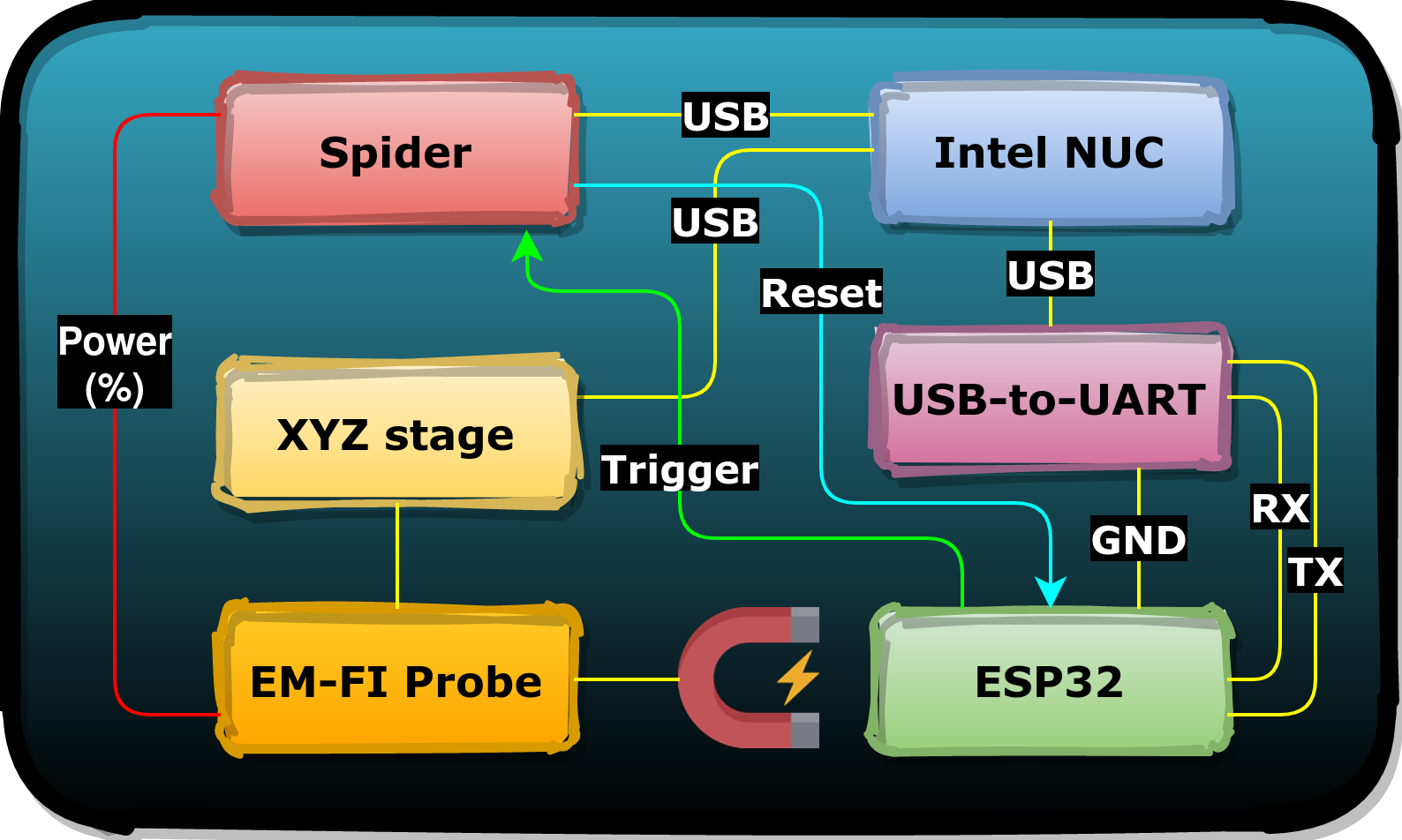
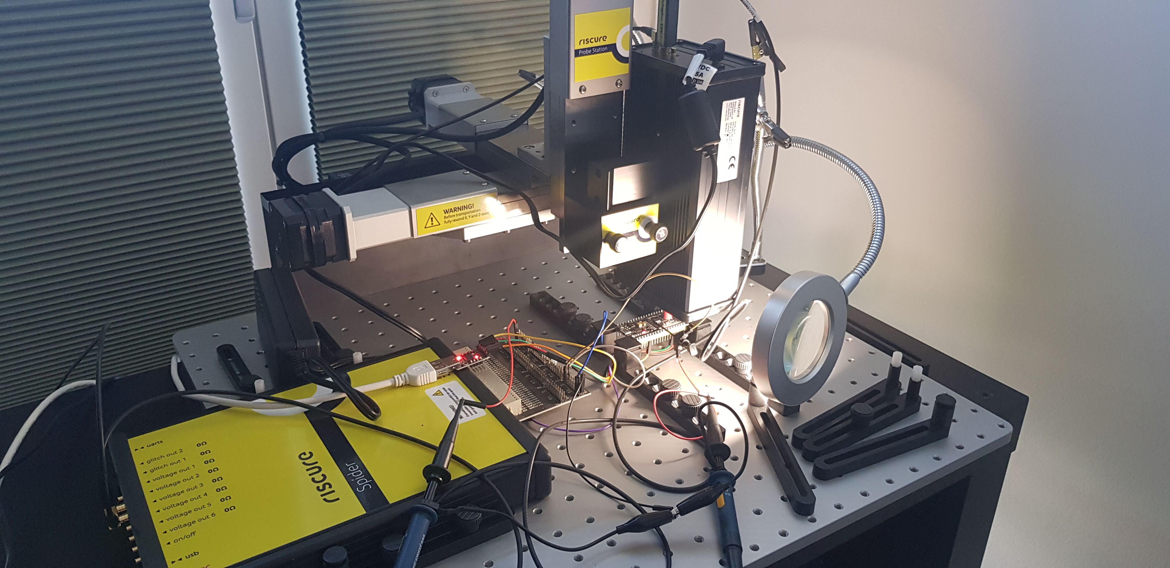
The picture below shows the setup in action, while we inject EM glitches into the ESP32.
Target
We used the ESP32 NodeMCU modules available from AZ Delivery which is shown in the picture below. These modules are designed around a ESP32-WROOM-32 package.
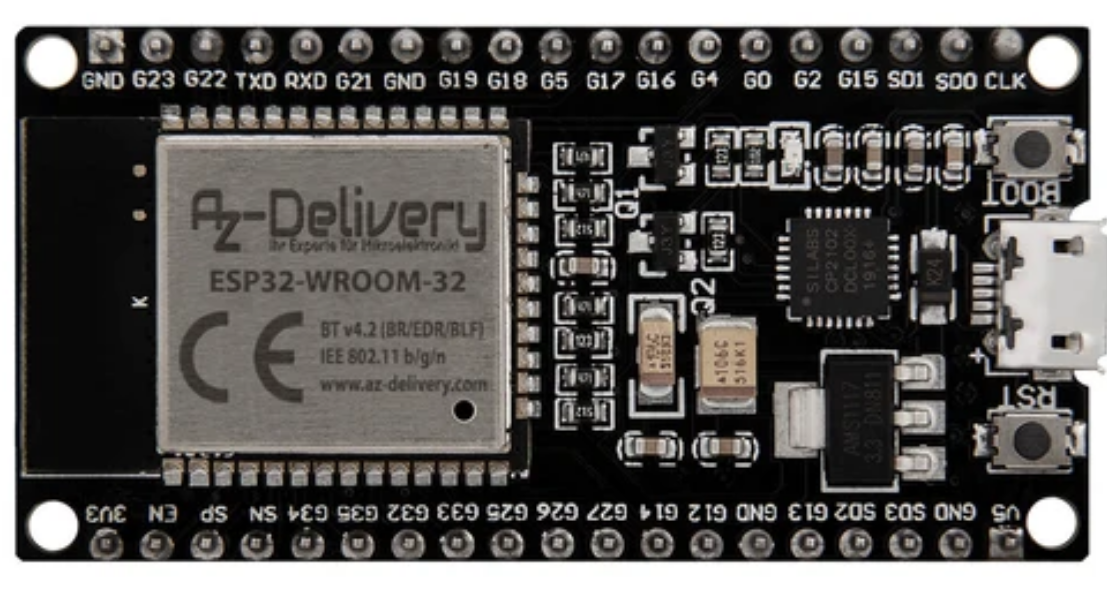
We removed the metal casing of the ESP32-WROOM-32 package in order to place the tip of the EM-FI Probe on the chip's surface. This is the only modification we made to the target in order to inject EM glitches.
Identification
The most important glitch parameters when performing EMFI, are position, power and timing. Tuning these parameters is not always trivial, especially when targeting something specific like Secure Boot. The combined parameter search space can be huge, especially if a fine grid is used for spatial positioning. Therefore, we typically start with an intermediate step that allows us to determine efficiently where exactly a chip is sensitive to EM glitches.
It's relevant to point out, that the first step for FI, after building the setup, is to determine if the target is vulnerable. As such vulnerability is at the chip level (i.e. hardware), it does not matter if it is identified on a development board or an finalized device (i.e. the vulnerability is the same). That's why, if possible, we typically prefer to perform the initial research using a development board that's designed around the same or similar chip. Then, porting the attack to a finalized device, especially when the software is the same as well (e.g. ROM code), is often trivial.
Test code
The test code we use during this intermediate step includes a command handler with at least one command, which does the following:
- receive command byte
- set trigger high
- using assembly to initialize unused registers with known values
- using assembly to increase a counter with add instructions (i.e add sled)
- set trigger signal low
- print the counter result
One of the implementations used during our ESP32 research is shown below. The test code allows us to identify a successful glitch by observing the counter printed on the serial interface. If the counter value is different than the expected value (i.e. 10,000), then the glitch we injected successfully affected the target's execution without preventing program continuation.
char cmd;
unsigned int counter;

while(1) {
	cmd = -1;
	uart_rx_one_char(&cmd);					// receive command

	if(cmd == 'A') {
		GPIO_OUTPUT_SET(26, 0);				// trigger high

		asm volatile (						// set unused registers
			"movi a0, 0x40404040;"
			"movi a1, 0x41414141;"
			"movi a2, 0x42424242;"
			"movi a3, 0x43434343;"
			"movi a4, 0x44444444;"
			"movi a5, 0x45454545;"
			// "movi a6, 0x46464646;"
			"movi a7, 0x47474747;"
			"movi a8, 0x48484848;"
			"movi a9, 0x49494949;"

			"movi a6, 0;"
			"addi a6, a6, 1;"				// start add sled
			< repeat 10,000 times >
			"mov %[counter], a6;"
			: [counter] "=r" (counter)
			:
			: 	"a6", "a0", "a1", "a2", "a3", "a4", "a5", "a7", "a8", "a9" );

		GPIO_OUTPUT_SET(26, 1);				// trigger low
	}

	printf("AAAA%08xBBBB\n", counter);	// send result back
}
We generate the trigger high and the trigger low signal by driving a GPIO pin. This allows us to create a measurable attack window that encompasses the sled of add instructions. This increases our chances of injecting a successful glitch and allows us to identify the presence of a hardware vulnerability.
Location
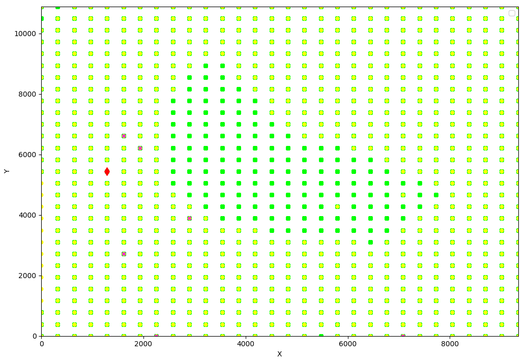
We use the XYZ stage to automatically move the EM-FI Probe across the chip's surface. The Spider waits until the trigger is set high, effectively injecting the glitch exactly within the attack window. The attack window is defined by the moment the trigger goes high and the trigger goes low. We randomize both the timing within the attack window and the power of the EM-FI Probe. We used a 30 x 30 grid for our initial experiment.
All experiments are grouped according to the behavior we observe. We assign a color to each experiment based on their group. All experiments that result in:
- no observable effect whatsoever are colored green dots
- a reset or mute of the chip are colored yellow dots
- a different counter value (i.e. successful glitch) are are colored red diamonds
- an exception (e.g. illegal instruction) are colored magenta crosses
We perform roughly 165,000 experiments in ~8.5 hours which are plotted in the graph shown below. For each experiment we move the EM-FI probe and randomize the glitch power between 10% and 100% of the maximum power.
The experiments are summarized below. For each type we provided an example of what is observed on the serial interface.
| Type | Response | Amount |
|---|---|---|
| Expected | AAAA00002710BBBB |
165404 |
| Exception | Fatal exception (0): IllegalInstruction |
6 |
| Reset/Mute | ets Jun 8 2016 00:22:57….rst:0x1 (POWERON_RESET) |
1489 |
| Success | AAAA0000270ABBBB |
1 |
The red diamond represents a location where we were able to introduce a successful glitch that introduced a fault that effected the increment of the counter without affecting the chip's continuation. Although we observed only a single successful glitch, it shows that the ESP32 is susceptible to EM glitches.
We achieved our first goal, we identified a hardware vulnerability. Let's see if we can exploit it by introducing faults that allow us to build an actual attack. We decided to fix the EM-FI probe to the location of the successful glitch the bypass of Secure Boot. This nicely reduces the glitch parameter search space by one entire dimension.
Exploitation
The Espressif IoT Development Framework (ESP-IDF) includes convenient tools to build software (idf.py), burn eFuses (espefuse.py), generate keys (espsecure.py) and program the flash memory (esptool.py). We used these tooling extensively throughout while finding ways to exploit the vulnerability.
Perform a sanity check
It's always a good idea to perform a so-called “sanity check” to verify if Secure Boot is actually enabled and works as expected. One approach for doing this, is to invalidate the bootloader and observe the differences on the serial interface output. When there is no serial interface output, other information may be used as well, such as the communication with the flash or the chip's power consumption. As fas as we know the serial interface output of the ESP32 cannot be disabled and therefore always available.
After power-on reset, the ROM ( green ) and bootloader ( red ) print the following:
+ ets Jun 8 2016 00:22:57
+
+ rst:0x1 (POWERON_RESET),boot:0x13 (SPI_FAST_FLASH_BOOT)
+ configsip: 0, SPIWP:0xee
+ clk_drv:0x00,q_drv:0x00,d_drv:0x00,cs0_drv:0x00,hd_drv:0x00,wp_drv:0x00
+ mode:DIO, clock div:2
+ load:0x3fff0008,len:4
+ load:0x3fff000c,len:3220
+ load:0x40078000,len:4816
+ load:0x40080400,len:18640
+ entry 0x40080740
- I (86) boot: Chip Revision: 1
- I (87) boot_comm: chip revision: 1, min. bootloader chip revision: 0
- I (42) boot: ESP-IDF v3.3.1 2nd stage bootloader
- I (42) boot: compile time 16:14:32
- I (42) boot: Enabling RNG early entropy source...
- I (46) boot: SPI Speed 		: 40MHz
- I (50) boot: SPI mode 		: DIO
- I (54) boot: SPI Flash Size	: 2MB
-
- Hello, I am the bootloader
We invalidate the bootloader by modifying the string bootloader, visible in the last line of the above serial interface output, into Raelize!!!. Then, we program the modified bootloader to the external flash of the ESP32. Then, when we boot up the ESP32, we observe the following output printed on the serial interface.
+ ets Jun 8 2016 00:22:57
+
+ rst:0x10 (RTCWDT_RTC_RESET),boot:0x13 (SPI_FAST_FLASH_BOOT)
+ configsip: 0, SPIWP:0xee
+ clk_drv:0x00,q_drv:0x00,d_drv:0x00,cs0_drv:0x00,hd_drv:0x00,wp_drv:0x00
+ mode:DIO, clock div:2
+ load:0x3fff0008,len:4
+ load:0x3fff000c,len:3220
+ load:0x40078000,len:4816
+ load:0x40080400,len:18640
+ csum err:0xb5!=0xdf
+ ets_main.c 371
The ROM verifies a checksum of the bootloader, which is invalid due to our modification. The checksum value present in the flash image is easily identified as the required information is printed on the serial interface. We simply change 0xb5 into 0xdf to satisfy the checksum operation. As expected, the ROM now reports that the Secure Boot check failed.
+ ets Jun 8 2016 00:22:57
+
+ rst:0x10 (RTCWDT_RTC_RESET),boot:0x13 (SPI_FAST_FLASH_BOOT)
+ configsip: 0, SPIWP:0xee
+ clk_drv:0x00,q_drv:0x00,d_drv:0x00,cs0_drv:0x00,hd_drv:0x00,wp_drv:0x00
+ mode:DIO, clock div:2
+ load:0x3fff0008,len:4
+ load:0x3fff000c,len:3220
+ load:0x40078000,len:4816
+ load:0x40080400,len:18640
+ secure boot check fail
+ ets_main.c 371
Now we have the Secure Boot implementation kick in, we can think about bypassing it by exploiting the hardware vulnerability we identified using EMFI.
Timing the attack
The identification phase allowed us to fix the *EM-FI Probe( location and give some insights into the power that's required. Unfortunately, the trigger based on a GPIO pin could not be used any more, as the verification is performed by the ROM code, which cannot be modified. Therefore, we needed a new reference point for timing our FI attack.
We started by using the reset signal as the trigger, but this induced significant jitter in our timing. Therefore, we decided to use the flash activity to time our attack. This is often a great signal to use for triggering as it is often tightly coupled to the software execution, especially during Secure Boot.
The activity on pin1 of the flash is shown in blue whereas the trigger signal that we derive from this activity is shown in red.
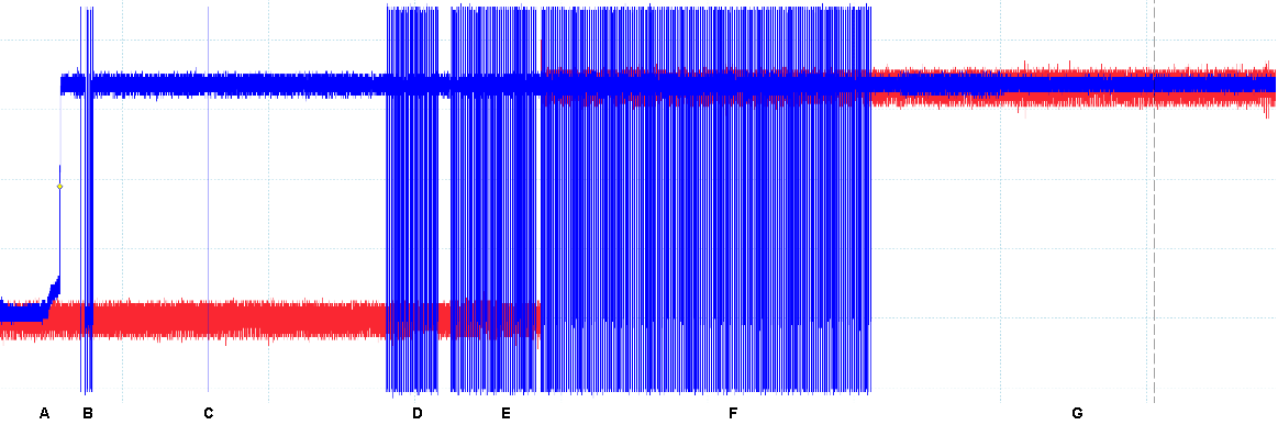
At this stage of the research, we did not exactly know what was happening at each moment (i.e. A to G). However, we know we take the chip out of reset just before A and we assume that the bootloader is copied last during F. If a valid bootloader is programmed on the flash, the chip starts executing the bootloader somewhere during G.
Performing the attack
We decided to inject glitches in a 10 µs attack window starting directly after F. The attack cycle for each experiment, which allowed us to perform roughly 10 experiments per second, was as follows:
- Pull the EN pin down to keep the chip in reset
- Pull the EN pin up to release the chip from reset
- Wait for 17 ms until the flash activity gap between E and F
- Wait for the first falling edge on pin1 of the flash (beginning of F) and set trigger high
- Inject an EM glitch with randomized power and timing within the attack window
- Store the serial interface output in a database for post processing
After ~35,000 experiments, which took ~55 minutes, we observed three successful glitches where we bypassed Secure Boot using a EM glitch. We can easily identify the successful glitches as Raelize!!! is printed on the serial interface instead of bootloader as is shown below.
+ ets Jun 8 2016 00:22:57
+
+ rst:0x1 (POWERON_RESET),boot:0x13 (SPI_FAST_FLASH_BOOT)
+ configsip: 0, SPIWP:0xee
+ clk_drv:0x00,q_drv:0x00,d_drv:0x00,cs0_drv:0x00,hd_drv:0x00,wp_drv:0x00
+ mode:DIO, clock div:2
+ load:0x3fff0008,len:4
+ load:0x3fff000c,len:3220
+ load:0x40078000,len:4816
+ load:0x40080400,len:18640
+ entry 0x40080740
- I (86) boot: Chip Revision: 1
- I (87) boot_comm: chip revision: 1, min. bootloader chip revision: 0
- I (42) boot: ESP-IDF v3.3.1 2nd stage bootloader
- I (42) boot: compile time 16:14:32
- I (42) boot: Enabling RNG early entropy source...
- I (46) boot: SPI Speed 		: 40MHz
- I (50) boot: SPI mode 		: DIO
- I (54) boot: SPI Flash Size	: 2MB
-
- Hello, I am the Raelize!!!
The plot below shows all the experiments where the X axis is the timing (nanoseconds) and the Y axis is the power (% of full power). The three red diamonds represent three successful glitches.

The statistics for these experiments are shown below.
| Type | Amount | % |
|---|---|---|
| Expected | 19494 | 56.54 |
| Reset/Mute | 14981 | 43.45 |
| success | 3 | 0.01 |
We can determine the attack's success rate by tuning the glitch parameters. When we simply take the exact same glitch parameters (i.e. position, power and timing) we achieve a success rate of 2 successful glitches per minute. This shows the attack can be easily reproduced once the glitch parameters are known.
Conclusion
We demonstrated that the ESP32 is vulnerable to EMFI and we leveraged this hardware vulnerability for a Secure Boot attack. Even though a similar attack has already been published, we demonstrated that EMFI brings significant advantages over other Fault Injection techniques.
For this Secure Boot attack, we did not assume any specific Fault Model as we merely leveraged the observable behavioral changes of the chip. Using a refined scanning technique, in combination with an efficient trigger for timing, was simply sufficient to build a successful Secure Boot attack.
Nonetheless, these initial results suggested to us that there may be an opportunity to leverage more refined Fault Models for exploitation. We anticipated, that we could put our previously published research into practice where we turn copy operations into execution primitives. If applicable, this could allow us to invent powerful new attacks that bypass more than just Secure Boot using a single glitch.
We actually tried a few different things after the initial attack described in this post. Like any research, not everything succeeded, but we actually managed to bypass Secure Boot and Flash Decryption using a creative and interesting approach.
"It's not the fault that matters,
 it's how you use it that reveals its true value." - Raelize
The results of this adventure beyond “just bypassing Secure Boot” will be described in a series of upcoming posts which will be published in the upcoming weeks. Stay tuned!
Acknowledgment
We would like to thank Espressif for their positive, proactive and investigative attitude during the entire coordinated disclosure of this research. Our experience was entirely positive and we wish all vulnerability disclosures would be like this. It sets a great example on how to deal with a coordinated vulnerability disclosure process.